
V
V
V
V
-
-
-
(Ta=25 ∞C)
(Unit : mm)
Features
Applications
Electro-optical Characteristics
Parameter Symbol
Conditions
MIN.
TYP.
MAX.
Unit
GL1F20
GL1F20
Infrared Communication
(IrDA1.0 Compatible)
InfraredEmitting Diode
1. IrDA1.0 compatible infrared emitting diode
2. Built-in infrared emitting diode circuit
1. Personal computers
2. Portable information terminal equipment
3. Printers
4. Word processors
3. Recommended use in combination with detector (
IS1U20
)
IrDA : Abbreviation of the Infrared Data Association established
for standardization of infrared communication specifications
CC
IH
V
IL
p
I
E
-
-
-
I
F
= 20mA
4.75
4.5
850
40
1.41
-
870
-
0.23
0.17
5.25
V
CC
0.4
900
350
0.6
0.6
V
nm
mW/sr
µ
s
µ
s
µ
s
(Transmission rate : 2.4 to 115.2kbps)
Terminal configuration
1.6
V
CC
= 5V,R
L
= 7.5
V
in
= 4.5V
t
win
= 1.63
µ
s,Duty ratio : 3/16
-
Driving voltage
High level input voltage
Low level input voltage
Peak emission wavelength
Radiant intensity
Light pulse width
Light rise time
Light fall time
Input current
Half intensity wavelength
Half intensity angle
I
IH
V
in
= 4.5V
I
F
= 20mA
I
F
= 20mA
-
1.0
-
3.0
40
± 20
-
-
-
nm
mA
*3 Direction of mechanical axis of the lens portion of the element :
=0∞
(Ta=25∞C)
T
opr
∞C
T
stg
∞C
T
sol
260
∞C
Absolute Maximum Ratings
Parameter
Symbol Rating
Unit
Operating temperature
Storage temperature
Soldering temperature
Forward current
Peak forward current
*2
*1
I
FM
I
F
50
400
- 10 to + 70
- 20 to + 85
mA
mA
*1 Pulse width 78.1
µ
s, Duty ratio=3/16
*2 For MAX. 3 seconds at the position of 2 mm from the resin edge
t
r
t
f
-
2.71
1 Base
2 Emitter
3 Anode
<=
15∞,*3
t
W
Outline Dimensions
5.6
R 1.4
2.2
4.0
2.5
1.0
17.9
MIN 0.3
3.6
MAX
.
0.6
3-0.45
1.27
1.27
Base
0.4
Transparent resin
1 2 3
1
2
3
Detector center
data books, etc. Contact SHARP in order to obtain the latest version of the device specification sheets before using any SHARP's device.
"
"
In the absence of confirmation by device specification sheets, SHARP takes no responsibility for any defects that occur in equipment using any of SHARP's devices, shown in catalogs,
s
s
s
s
s
General Descriptions of IrDA1.0 System
Transmission rate : 2.4k to 115.2kbps
Modulation system : SIR
Receiving distance : 1 m
Transmitting wavelength : 850 to 900 nm
Receiving waveform : As shown in the right drawing
Output waveform : As shown in the right drawing
100
0
25
50
75
0
- 25
Ambient temperature Ta (∞C)
500
400
300
200
100
70
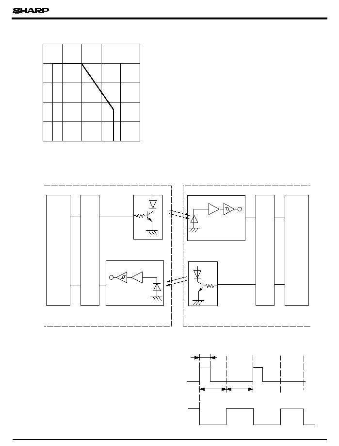
Fig. 1 Peak Forward Current vs. Ambient
Temperature
Infrared Communication Terminal System Configuration Using GL1F20/IS1U20
- 10
Peak forward current I
FM
(
mA
)
Pulse width 78.1
µ
s
Duty ratio= 3/16
Please refer to the chapter "Precautions for Use". (Page 78 to 93)
Receiving waveform
Output waveform
(3/16) T
0
1
0
1
T
T
T =8.6 to 417
µ
s
Serial
∑
parallel converter circuit
Serial
∑
parallel converter circuit
Modulator/remodulator circuit
Light emitting device for
infrared communication
(
GL1F20
)
Light emitting device for
infrared communication
(
GL1F20
)
OPIC detecting device for
infrared communication
(
IS1U20
)
OPIC detecting device for
infrared communication
(
IS1U20
)
Comparator
Amp
Amp
OA equipment body such as portable information terminal equipment
OA equipment body such as portable information terminal equipment
Comparator
Modulator/remoldulator circuit
GL1F20
s
s
q