 | –≠–ª–µ–∫—Ç—Ä–æ–Ω–Ω—ã–π –∫–æ–º–ø–æ–Ω–µ–Ω—Ç: GP1A34LC | –°–∫–∞—á–∞—Ç—å:  PDF PDF  ZIP ZIP |
GP1A34LC
GP1A34LC
*1 Collector-emitter voltage of output transistor
*2 Collector current of output transistor
*3 The connector should be plugged in/out and the unit's hook should
be used at normal temperature.
Parameter
Symbol
Rating
Unit
Supply voltage
V
CC
- 0.5 to + 7
V
*1
Output voltage
V
O
- 0.5 to + 13
V
*2
Low level output current
I
OL
10
mA
*3
Operating temperature
T
opr
- 20 to + 75
∞C
*3
Storage temperature
T
stg
- 30 to + 85
∞C
s
Absolute Maximum Ratings
(Ta = 25∞C )
OPIC Photointerrupter with Con-
nector
s
Features
s
Applications
1. Snap-in mounting type
2. Can be mounted on 2 different thickness
boards
( 1.0mm, 1.6mm ) .
3. Uses 3-pin connector terminal
4. High sensing accuracy ( Slit width : 0.5mm )
5. Wide gap between light emitter and detec-
tor ( 5mm )
1. Copiers, printers, facsimiles
s
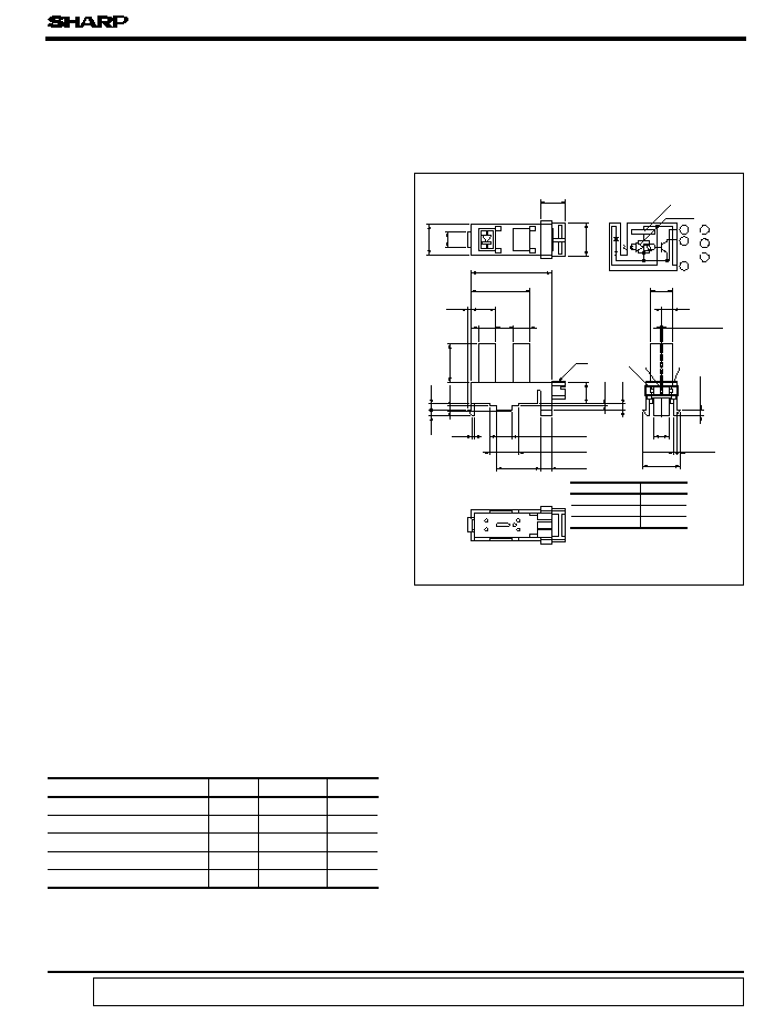
Outline Dimensions
(Unit : mm )
4.0
8.4
(3.9)
( 9.0
)
21.8
16.0
6.5
0.9
5.0 4.5
4.5
10.5
1.5
1.7
1.6
0.9
5.9
0.6
1.7
g
3.0
6.0
Slit width
4.0
10.2
Amp.
Voltage regulator
Internal connection diagram
1
2
3
2 GND
1
2
3
2
-
11.8
2
-
4.0
2
-
8.0
2
-
3.0
2
-
0.9
2
-
0.9
2
-
1.6
Dimensions(d) Tolerance
d
<
5.0
±
0.15
5.0
<=
d
<
15.0
±
0.2
15.0
<=
d
±
0.3
g
JAPAN AMP made connector
gg Recommended connectors on the inserted side
are shown on the page after next.
An OPIC consists of a light-detecting element and signal-
processing circuit integrated onto a single chip.
*"OPIC" ( Optical IC ) is a trademark of the SHARP Corporation.
data books, etc. Contact SHARP in order to obtain the latest version of the device specification sheets before using any SHARP's device.
"
"
In the absence of confirmation by device specification sheets, SHARP takes no responsibility for any defects that occur in equipment using any of SHARP's devices, shown in catalogs,
*
Unspecified tolerances shall be as follows
;
*
( )
:
Reference dimensions
Ultrex 172681-3
Recommended connector on the inserted side
1 V
O
3 V
CC
0.5
±
0.1
172685-3, etc.
gg
GP1A34LC
s
Electro-optical Characteristics
( V
CC
= 5V, Ta= 25∞C)
Parameter
Operating supply voltage
Low level supply current
Low level output voltage
High level supply current
High level output voltage
Response frequency
Rise time
Fall time
Symbol
Conditions
MIN.
TYP.
MAX.
Unit
V
CC
4.5
-
5.5
V
I
CCL
Light beam uninterrupted
-
-
30
mA
V
OL
Light beam uninterrupted, I
OL
= 2.5mA
-
-
0.4
V
I
CCH
Light beam interrupted
-
-
30
mA
V
OH
Light beam interrupted, R
L
= 47k
V
CC
x 0.9
-
-
V
f
L
= 47k
, -
-
-
Hz
t
r
R
L
= 280
0.1
0.5
µ
s
t
f
-
0.05
0.5
µ
s
Response
time
Disk
2.0
90 %
10 %
t
r
t
f
0.8
0.8
0
2
4
6
8
10
12
- 20
100
75
50
25
0
0.05
0.02
0.01
0.1
0.2
0.5
1
50
20
5
2
100
10
1
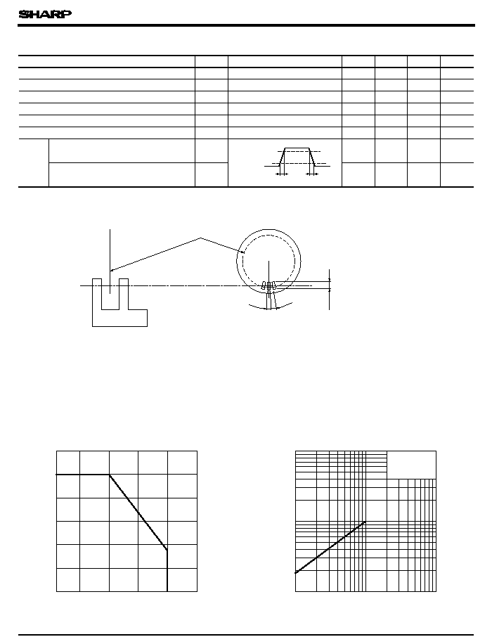
Fig. 1 Low Level Output Current vs.
Ambient Temperature
Fig. 2 Low Level Output Voltage vs.
Low Level Output Current
Low level output current I
Ambient temperature T
a
(∞C)
OL
(
V
)
Low level output current I
OL
( mA )
V
CC
= 5V
T
a
= 25∞C
OL
(
mA
)
Low level output voltage V
*5
*4
R
3 000
*5 Response frequency is measured with the disk shown below being rorated. ( Unit : mm )
*4 Output should not be DC level
GP1A34LC
20
10
0
5.5
5.0
4.5
30
0.6
0.5
0.1
0
0.2
0.3
0.4
100
75
50
25
0
- 25
5mA
2.5mA
+ 25∞C
+ 75∞C
{
h
Shield
7
6
5
4
3
2
1
Shield distance h ( mm )
0
0
Shield distance d ( mm )
1
2
3
4
5
6
7
Shield
d
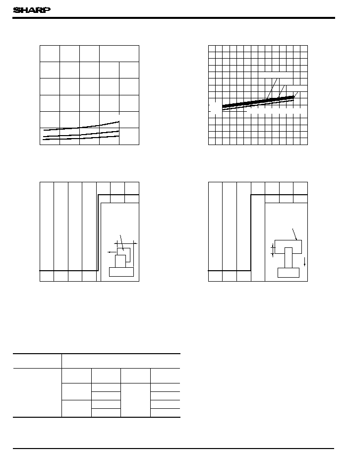
Fig. 3 Low Level Output Voltage vs.
Ambient Temperature
Fig. 5 Detecting Position Characteristics (1)
Fig. 6 Detecting Position Characteristics (2)
OL
(
V
)
Ambient temperature T
a
(∞C)
V
CC
= 5V
I
OL
= 10mA
Supply current I
CC
(
mA
)
Supply voltage V
CC
( V)
I
CCL
I
CCH
T
a
=- 20∞C
T
a
=- 20∞C, + 25∞C, + 75∞C
V
CC
= 5V
T
a
= 25∞C
R
L
= 47k
Detecting position d = 4.2
± 0.3
mm
V
CC
= 5V, T
a
= 25∞C
R
L
= 47k
Detecting position h= 3.0
+ 2.0
- 1.5
mm
s
Recommended Connentors on the Inserted Side
172685-3
s
Recommended Mounting Holes
Same as
GP1S09
Housing
Model No.
172677-3
Special
terminal
Model No.
AWG
size
Product
shape
Material
Model No.
AWG
30 to 26
Chain
Copper
phosphide
171609-1
171611-1
Bulk
AWG
26 to 22
Chain
171610-1
171612-1
Bulk
Low level output voltage V
Fig. 4 Supply Current vs. Supply Voltage
Output
OFF
Output
ON
Output OFF
Output ON
(mass termination type )
(Solderless type )
q
JAPAN AMP made Ultrex connector
q
JAPAN AMP made Ultrex connector

s
Precautions for Use
GP1A34LC
( 1) In this product, the PWB is fixed with a hook, and cleaning solvent may remain inside
( 2) Remove dust or stains, using an air blower or a soft cloth moistened in cleaning slovent.
( 3) In order to stabilize power supply line, connect a by-pass capacitor of more than 0.01
µ
F
between Vcc and GND near the device.
( 4) As for other general cautions, refer to the chapter " Precautions for Use ".
the case; therefore, dip cleaning or ultrasonic cleaning are prohibited.
However, do not perform the above cleaning using a soft cloth with cleaning solvent in the
marking portion.
In this case, use only the follwing type of cleaning solvent used for wiping off:
Ethyl alcohol, Methyl alcohol, Isopropyl alcohol
When the cleaning solvents except for specified materials are used, please consult us.