
s
Absolute Maximum Ratings
(Ta= 25∞C )
s
Applications
s
Features
( Unit : mm)
GP1S44S1
GP1S44S1
2. Easy wiring due to built-in connector
2. Laser beam printers
3. Facsimiles
1. Copiers
Paramerter
Symbol
Rating
Unit
Supply voltage
V
CC
V
*1
Output voltage
V
O
35
V
*2
Output current
I
C
20
mA
*3
Output power dissipation
P
O
75
mW
*4
Operating temperature
T
opr
- 20 to + 75
∞C
*4
T
stg
- 40 to + 85
∞C
*2 Collector current of phtotransistor
*4 The connector should be plugged in/out at normal temperature.
- 0.5 to + 10
3. Snap-in mounting type in order to
mount to an equipment easily
15.3
(0.5)
8.0
18.0
17.2
1.5
R0.5
1.5
0.8
17.0
16.8
13.8
11.4
9.9
( 8,0
)
6.9
5.4
6.2
4.0
( 9.35
)
11.0
( 8.0
)
1.0
0.6
0.2
1.5
12.8
10.8
(5.0)
g
15.5
1
2
3
Internal connection diagram
1 GND
1. High sensing accuracy ( Slit width : 0.5mm )
*3 Collector dissipation of phototransistor
*
Tolerance
:±
0.3mm
*
( )
:
Reference dimensions
g
DF3A-3P-2DSA made by
1
2
3
Transmissive Type
Photointerrupter with Actuator
Storage temperature
*1 Collector-emitter voltage of phtotransistor
1.0
2.4
(5.0)
s
Outline Dimensions
HIROSE Japan Co. Ltd.
data books, etc. Contact SHARP in order to obtain the latest version of the device specification sheets before using any SHARP's device.
"
"
In the absence of confirmation by device specification sheets, SHARP takes no responsibility for any defects that occur in equipment using any of SHARP's devices, shown in catalogs,
(20
∞
)
2 V
CC
3 V
OUT
GP1S44S1
*
Phototransistor between A point and
C point shall be ON-state when
from normal condition A point to C point
in Fig.1. At this time, L
C
of phototransistor
*
I
C
is an actual measurement value
s
Electro-optical Characteristics
Lever starting torque : 1x 10 N ∑ m or less
( Lever reciprocating operation between
normal condition B point and C point
at the condition of no load. )
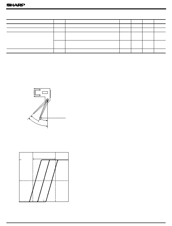
Actuator Lever Angle
ON-state range of PT (
*
Ic/2 )
32
37
42
0
50
100
20
∞
Normal position
( Unless otherwise specified, V
CC
= 5V, Ta= 25∞C )
Parameter
Symbol
MIN.
TYP.
MAX.
Unit
Dissipation current
I
CC1
Light beam interrupted
-
-
20
mA
Dissipation current
I
CC2
Light beam uniterrupted
-
-
20
mA
Collector current
I
C1
I
C2
Light beam interrupted, V
O
= 5V,
without external disturbing light illuminance
-
-
0.05
mA
Light beam uninterrupted, V
O
= 5V
without external diturbing light illuminance
0.25
-
-
mA
Operating supply voltage
V
CC
Ta=-20 to + 75∞C
4.5
5.0
5.5
V
C point
A point
B point
Relative output of I
C
(
%
)
C
vs.
∞
on collector current in electro-optical characte-
ristics.
Normal condition B point shall be opaque con-
dition.
s
Mechanical Characteristics
s
Lever Life
- 4
Condition of light beam interrupted : Lever is normal condition on the Fig.1
Condition of light beam uniterrupted : Lever is 30∞ or more movement condition from A point to B point on Fig.1
the actuator lever rotated ( 37∞ ± 5∞ )
Fig. 2 Relative Output of I
Actuator lever angle ( )
Conditions
100 000 times or more
Fig. 1 Detecting Position
shall be (
*
I
C
/2 ) .

GP1S44S1
0
25
50
0
100
80
60
40
25
20
75
Fig. 3 Power Dissipation vs.
Ambient Temperature
- 20
Ambient temperature T
a
(∞C)
Power dissipation P
O
(
mW
)
10
8
6
4
2
0
0
1.0
2.0
3.0
4.0
5.0
Output Voltage
V
cc
= 5.5V
V
cc
= 5V
V
cc
= 4.5V
T
a
= 25∞C
Output voltage V
O
(V)
Collector current I
C
(
mA
)
0
25
50
75
3
2
1
85
4
Fig. 5 Collector Current 2 vs. Ambient
Temperature (Light Beam Uninterrupted )
- 25
Ambient temperature T
a
(∞C)
Collector current I
C2
(
mA
)
0.30
0.25
0.20
0.15
0.10
0.05
100
75
50
25
0
0
Ambient Temperature
- 30
Ambient temperature T
a
(∞C)
O
( sat
)
(
V
)
V
CC
= 5V
I
C2
= 0.125mA
light beam
uninterrupted
0
25
50
75
0
0.06
0.04
0.02
85
0.08
0.1
Fig. 7 Collector Current 1 vs. Ambient
Temperature (Light Beam Interrupted )
- 25
Ambient temperature T
a
(∞C)
Collector current I
C1
(
mA
)
75
100
Fig. 4 Collector Current vs.
Fig. 6 Output Saturation Voltage vs.
Output saturation voltage V
q
Please refer to the chapter " Precautions for Use " .