
Features
Applications
Outline Dimensions
(Unit : mm)
3. Power filter capacitor and resistance are not required any more
as a result of adoption of built-in constant voltage circuit
4. Various B.P.F. (Band Pass Frequency) frequency to meet different user needs
1. AV equipment such as TV sets,
VCRs and audio equipment
2. HA equipment such as air conditioners
and electric fans
GP1U26R/27R/28R/28Q Series
1. Anti electromagnetic induction noise type
2. Compact (case volume)
(
GP1U28Q
: About 1/4 compared with
GP1U78Q
)
GP1U26R Series
GP1U27R Series
GP1U28R Series
GP1U28Q Series
1. Unspecified tolerance :
�
0.3
2.
*
1 : The dimension of lead base
1. Unspecified tolerance :
�
0.3
2.
*
1 : The dimension of lead base
1. Unspecified tolerance :
�
0.3
2.
*
1 : The dimension of lead base
1. Unspecified tolerance :
�
0.3
2.
*
1 : The dimension of lead base
GP1U26R/GP1U27R Series
GP1U28R/GP1U28Q Series
Anti Electromagnetic Induction
Noise Type Compact IR Detecting
Unit for Remote Control
1 V
out
2
2
V
CC
3
3
GND
1
1
V
out
2
2
V
CC
3
3
GND
1
1
V
out
2
2
V
CC
3
3
GND
1 V
out
2 V
CC
3 GND
Detector
center
26
S
7.3
2
0.5
3.4
13.1
*1
*1
*1
10.2
2.54
2.54
4
3.75 3.75
2-0.5
2-0.4
2-0.75
2-0.75
0.6
0.6
5.2
3.6
Marking
0.4
1.7
10.45
(9.7)
1.7
8.75
1.4
1.4
2.8
1.1
0.3
+0.5
1.2
1.2
2.54
2.54
(0.5)
0.8
Recommended drilling as viewed from the soldering face.
-
4.5
Detector
center
27
S
7.3
2
0.5
3.4
13.1
*1
*1
*1
10.2
2.54
2.54
4
3.75 3.75
2-0.5
2-0.4
2-0.75
2-0.75
0.6
0.6
10.4
3.6
Marking
0.4
1.7
10.45
(9.7)
1.7
8.75
1.4
1.4
2.8
1.1
-0.3
+0.5
1.2
1.2
2.54
2.54
(0.5)
0.8
Recommended drilling as viewed from the soldering face.
4.5
Detector
center
28
S
7.3
2
0.5
3.4
13.1
*1
*1
*1
10.2
2.54
2.54
4
3.75 3.75
2-0.5
2-0.4
2-0.75
2-0.75
0.6
0.6
14.4
3.6
Marking
0.4
1.7
10.45
(9.7)
1.7
8.75
1.4
1.4
2.8
1.1
-0.3
+0.5
1.2
1.2
2.54
2.54
(0.5)
0.8
Recommended drilling as viewed from the soldering face.
4.5
28
S
7.3
0.5
0.6
0.6
0.5
2.54
2.54
2.54
2.54
1.2
1.2
3.75
3.75
3.65
1.95
1.7
1.7
0.8
Recommended drilling as viewed from the soldering face.
0.4
1.6
3.7
1.4
1.4
5.4
6.8
2
4
Marking
3.6
13
3.4
*1
*1
1 2 3
1
data books, etc. Contact SHARP in order to obtain the latest version of the device specification sheets before using any SHARP's device.
"
"
In the absence of confirmation by device specification sheets, SHARP takes no responsibility for any defects that occur in equipment using any of SHARP's devices, shown in catalogs,
s
s
s

kHz
Vout
Vcc
GND
B.P.F.
Internal Block Diagram
Limiter
Demodulator
Integrator Comparator
Model Line-ups
B.P.F. center frequency
Model No.
Unit
40
36
38
36.7
32.75
56.8
Diversified models with a different B.P.F. frequency are also available.
(Ta=25�C)
V
CC
V
T
opr
�C
T
stg
�C
T
sol
260
�C
Absolute Maximum Ratings
Parameter
Symbol
Rating
Unit
*1
*2
Supply voltage
Operating temperature
Storage temperature
Soldering temperature
0 to 6.3
- 10 to + 70
- 20 to + 70
*1 No dew condensation is allowed.
*2 For 5 seconds
V
CC
V
Recommended Operating Conditions
Parameter
Symbol Operating conditions
Unit
Supply voltage
4.7 to 5.3
GP1U26R/27R/28R/28Q Series
GP1U26R
GP1U260R
GP1U261R
GP1U262R
GP1U263R
GP1U267R
GP1U27R
GP1U270R
GP1U271R
GP1U272R
GP1U273R
GP1U277R
GP1U28R
GP1U280R
GP1U281R
GP1U282R
GP1U283R
GP1U287R
GP1U28Q
GP1U280Q
GP1U281Q
GP1U282Q
GP1U283Q
GP1U287Q
s
s
s
s

CC
(Ta=25�C, V =+5V)
600
�
s
600
�
s
I
CC
-
-
5.0
mA
V
OH
V
CC
- 0.5
-
-
V
V
OL
-
-
0.45
V
T
1
400
-
800
�
s
T
2
400
-
800
f
O
-
-
-
kHz
Parameter
Symbol
Conditions
MIN.
TYP.
MAX.
Unit
Dissipation current
High level output voltage
Low level output voltage
High level pulse width
Low level pulse width
No input light
*3
20cm
10k
+
5V
10
�
F
PD49PI
10k
Vout
Performance
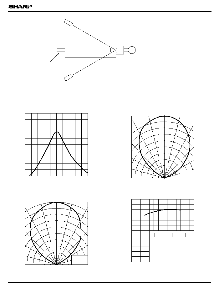
Using the transmitter shown in Fig. 1, the output signal of the light detecting unit is good enough to meet the following items in the standard optical system in Fig. 2.
(1) Linear reception distance characteristics
When L=0.2 to 6.5 m, Ee < 10 lx and
=0� in Fig. 2, the output signal shall meet the electrical characteristics in the attached list.
(2) Sensitivity angle reception distance characteristics
When L=0.2 to 4.5 m, Ee < 10 lx and
<= 30 � in Fig. 2, the output signal shall meet the electrical characteristics in the attached list.
(3) Anti outer peripheral light reception distance characteristics
When L=0.2 to 3 m, Ee <= 300 lx and
=0� in Fig. 2, the output signal shall meet the electrical characteristics in the attached list.
f
O
= *
4
Duty 50
%
Oscilloscope
Fig. 1 Transmitter
V
GP1U26R/27R/28R/28Q Series
Electrical Characteristics
B.P.F. center frequency
*4
*4 The B.P.F. center frequency fo varies with model, as shown in s
Model Line-ups
.
Burst wave
f
O
= *
4 kHz
Duty 50
%
*3 The burst wave as shown in the following figure shall be transmitted by the transmitter shown in Fig. 1.
The carrier frequency of the transmitter, however, shall be same as *4, and measurement shall be taken of the 100th and subsequent pulses after start of transmission.
*5 It refers to detector face illuminance.
*6 Outer peripheral light source : CIE standard light source A shall be used and placed at 45 � from perpendicular axis at the detector face center.
Transmitter (GL521 used)
In the above figure, the transmitter should be set so that the output V can be 40mV .
However, the
PD49PI
to be used here should be of the short-circuit current I =2.6
�
A at E =100 lx.
(E is an illuminance by CIE standard light source A (tungsten lamp).)
out
P - P
SC
*5
*5
*6
V
s
s
- 40
- 20
0
20
40
60
80
100
20
0
40
60
80
100
120
Ambient temperature Ta (�C)
Relative reception distance (%)
Unit
SHARP
standard transmitter
Relative comparison with reception
distance at V =5V,
=0� , Ee <10 lx
and Ta=30 �C taken as 100%
CC
Vout
Fig. 2 Standard optical system
Transmitter
Reception distance : L
Light detector face illuminance : Ee
(
indicates horizontal and vertical directions.)
GP1U26R/27R/28R/28Q Series
Fig. 1 B.P.F. Frequency Characteristics
[TYP.](GP1Uxx1R)
Fig. 2 Sensitivity Angle (Horizontal Direction)
Characteristics [TYP.] for Reference
Fig. 3 Sensitivity Angle (Vertical Direction)
Characteristics [TYP.] for Reference
Fig. 4 Relative Reception Distance vs. Ambient
Temperature [TYP.] for Reference
0
Angular displacement
0�
+ 90�
100
Relative reception distance (%)
+ 30�
+ 45�
+ 60�
+ 75�
- 90�
- 30�
- 45�
- 60�
- 75�
- 15�
+ 15�
80
60
40
20
0
Angular displacement
0�
Relative reception distance (%)
+ 90�
+ 30�
+ 45�
+ 60�
+ 75�
- 90�
- 30�
- 45�
- 60�
- 75�
- 15�
+ 15�
20
40
60
80
100
Carrier frequency (kHz)
Relative sensitivity (2dB/div)
28
30
32
34
36
38
40
42
44
46
48
V
CC
= 5V
Ta= 25�C
V
CC
= 5V
Ta = 25�C
0
14
1
2
3
4
5
6
7
8
9 10 11 12 13
0
100
200
300
700
400
500
600
Unit
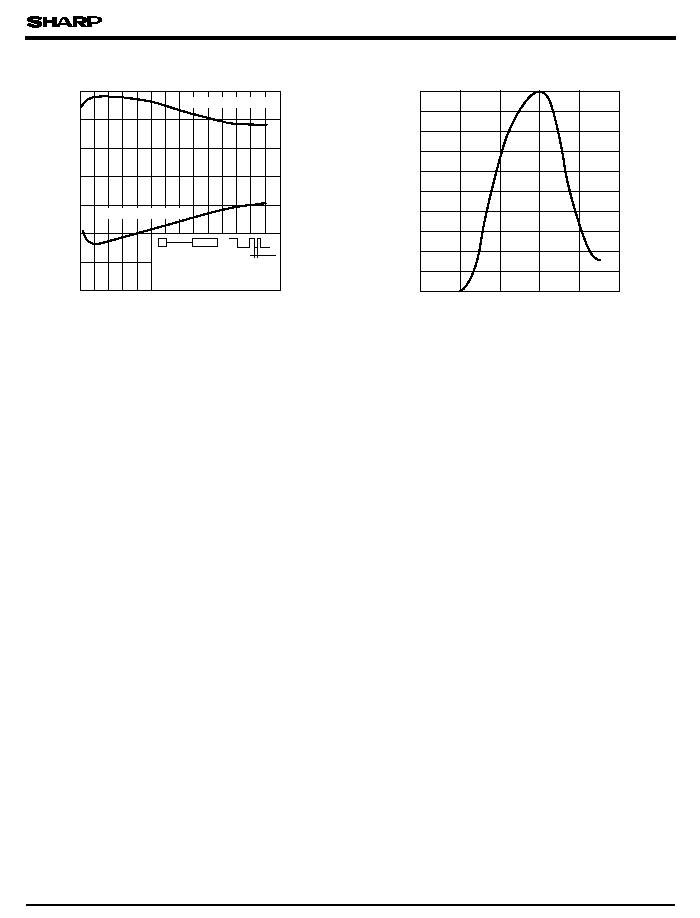
1st bit
AEHA code
generating transmitter
V =5V, Ta=RT,
=0� ,
Ee < 10 lx, T=430
�
s
Reception distance (m)
Relative sensitivity (%)
Wavelength
(nm)
GP1U26R/27R/28R/28Q Series
Fig. 6 Spectral Sensitivity for Reference
Pulse width (
�
s)
Fig. 5 AEHA (Japan Association of Electrical Home Appliances)
Code Pulse Width Characteristics (1st Bit) [TYP.] for Reference
High level pulse width
Low level pulse width
700
800
900
1000
1100
1200
10
20
30
40
50
60
70
80
90
100
CC
Precautions for Operation
1) In case of adopting the infrared light detecting unit for the wireless remote control, use it in accordance
with the transmission scheme and the signal format recommended in "Countermeasures for malfunction prevention of
home appliances with remote control" issued from Japan Association of Electrical Home Appliances (AEHA) in July, 1987.
Use of a transmission scheme and a signal format different from those recommended may cause malfunction of home appliances.
(Example : signal format without leader signal, bit structure of small duty ratio (T /(T +T )))
2) Use the light emitting unit (remote control transmitter), in consideration of performance, characteristics,
operating conditions of light light emitting device and the characteristics of the light detecting unit.
3) Pay attention to a malfunction of the light detecting unit when the surface is stained with dust and refuse.
Care must be taken not to touch the light detector surface.
If it should be dirty, wipe off such dust and refuse with soft cloth so as to prevent scratch. In case some solvents are required,
use methyl alcohol, ethyl alcohol or isopropyl alcohol only.
Also, protect the light detecting unit against flux and others, since their deposition on the unit inside causes reduction of the function,
fading of markings such as the part number.
4) The shield case should be grounded on PWB pattern.
(The area across the shield case and the GND terminal is internally conductive in some cases and non-conductive in some other cases.)
5) Do not apply unnecessary force to the terminal and the case.
6) Do not push the light detector surface (photodiode) from outside.
7) To avoid the electrostatic breakdown of IC, handle the unit under the condition of grounding with human body, soldering iron, etc.
8) Do not use hole and groove set in the case of the light detecting unit for other purposes,
since they are required to maintain the specified performance.
H
H
L
s