IrDA Technical Information
1
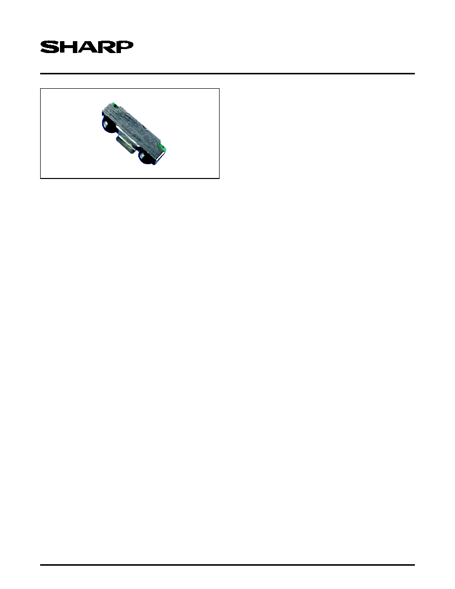
GP2W0110YPS/GP2W0114YPS
IrDA Technical Information
Low Power Infrared Transceiver
FEATURES
∑ IrDA Low Power Option Compatibility for Telecom-
munication and Mobile Terminals
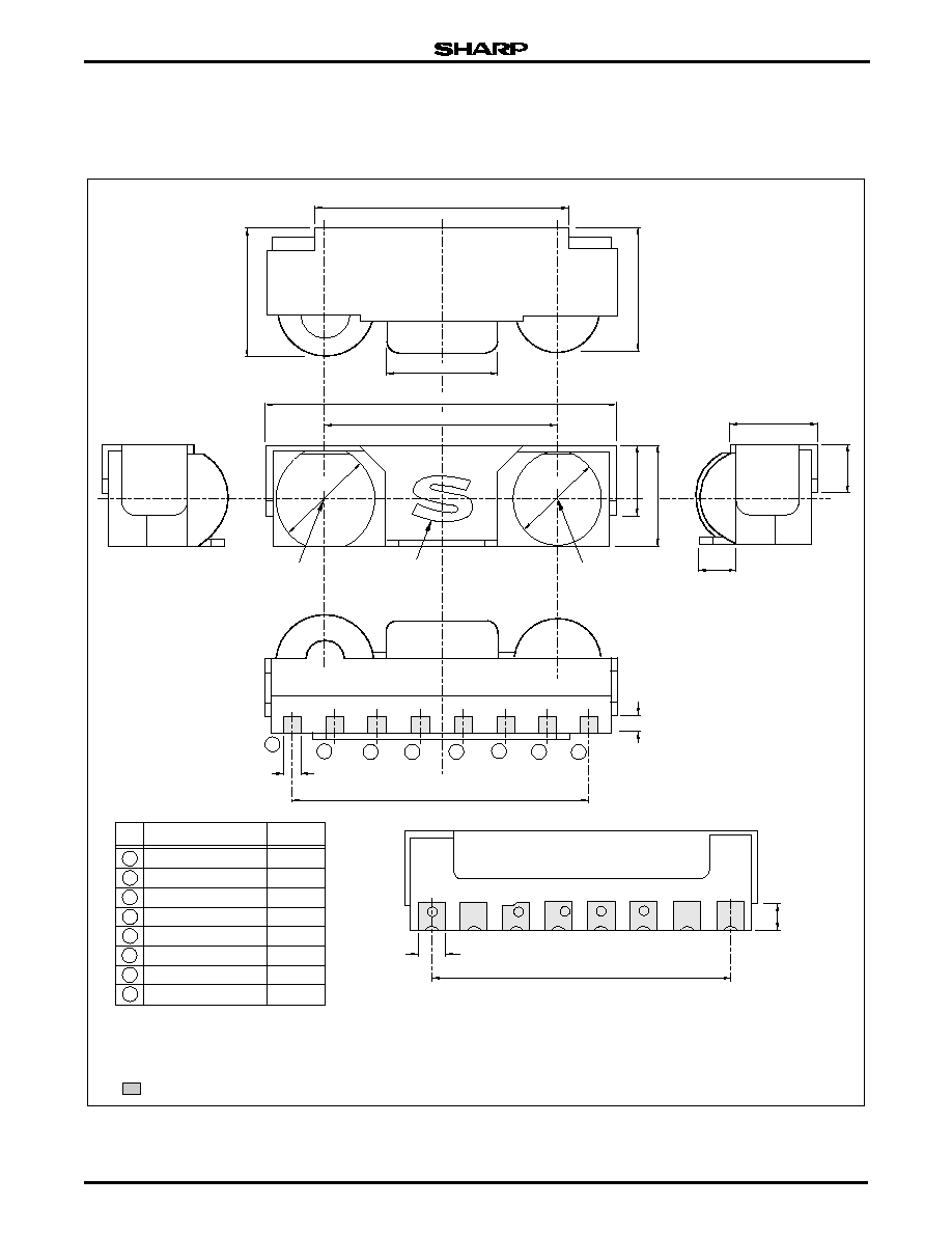
∑ Industry Low Volume Package Design for a Low
Power Transceiver:
≠ 7.6(W) ◊ 2.65(D) ◊ 2.0(H) mm, 40.28 mm
3
∑
Low Power Consumption with Built-in Shut-Down
Mode 0.2
µA (TYP.)
∑ Low and Wide Range Operating Voltage:
≠ V
DD
= 2.0 V to 3.6 V, V
LEDA
= 2.0 V to 6.0 V
∑ Soldering Reflow Capable
∑ SMD Lead-less Package Design Provides Flexibility
with either Vertical Mount or Horizontal Mount to PCBs
∑ Replaces GP2W0102YP, GP2W0104YP, and
GP2W0106YP
∑ Added Features include Tri-state Output and Split-
voltage Supply Capability
∑ Fully Compatible with Agilent HSDL 3201
∑ TOP View Version: GP2W0114YPS
APPLICATIONS
∑ Telecommunication Products
≠ Cellular Phones
≠ Pagers
≠ Smart Phones
∑ Mobile Products
≠ PDAs
≠ Electronic Wallets
≠ Mini-Notebook PCs
∑ Imaging Products
≠ Portable Printers
≠ Portable Text Scanners
DESCRIPTION
The SHARP GP2W0110YPS/GP2W0114YPS are
low-power, short-range infrared transceiver modules.
They meet the Mobile Communication Low Power
Option within the IrDA Specification for the 20 cm com-
munication range. When operating at lower supply volt-
ages, these units provide a reliable interface between
logic and IR signals. Applications include through-air,
serial, half-duplex IR wireless data links at rates up to
115 kbit/s and the devices are designed to satisfy the
IrDA Physical Layer Specifications.
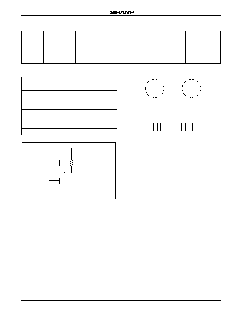
The SHARP GP2W0110YPS/GP2W0114YPS
infrared transceiver modules contain a high speed,
high efficiency, low power consumption AlGaAs LED,
silicon PIN photodiode, and the low power driven bipo-
lar integrated circuit. The IC contains a LED driver cir-
cuit and a receiver that provides the Rx output
supporting 2.4 kbit/s to 115.2 kbit/s IrDA signals. They
meet the IrDA Low Power Option Communication
Standard link distance of 0.2 m with low power devices
and 0.3 m with standard devices.
The GP2W0110YPS/GP2W0114YPS include a con-
stant-current source in the LED driver circuit that elimi-
nates the need for an external current limiting resistor in
the LED circuit.
The IrDA Low Power Option Standard is most suit-
able for telecommunication products and mobile termi-
nals, such as cellular phones, paging devices, and
PDA-cellular combined multimedia devices. The trans-
ceiver modules provide wireless data link capability for
cellular phones and pagers, PDAs, or any other IrDA
application already on the market.
The transceiver modules' receiver electronics oper-
ate at voltages from 2.0 V through 3.6 V without any
performance degradation. The split-voltage supply
allows the LED voltage to come from a separate supply.
An example is in cell phones where the LED may oper-
ate from the battery and the receiver and logic section
is supplied from a regulated supply at a lower voltage.
This provides manufacturers with the advantage of an
energy saving design in any application field, with alter-
natives for supply voltage and flexibility for other compo-
n e n t s . T h e G P 2 W 0 1 1 0 Y P S / G P 2 W 0 1 1 4 Y P S
transceiver modules have a built-in 0.1
µA Shutdown
mode for those applications that are very conscious
a b o u t c u r r e n t c o n s u m p t i o n . A d d i t i o n a l l y , t h e
GP2W0110YPS/GP2W0114YPS have a tri-state out-
put, which allow their use in applications where one port
connection may be connected to more than one device.
The included shield is appropriate in applications
where Electro-Magnetic Interference (EMI) is a con-
cern. Infrared energy is immune to EMI, but the receiv-
ing PIN photodiode is somewhat sensitive to EMI. This
is the case in all IR communication devices.

Low Power Infrared Transceiver
GP2W0110YPS/GP2W0114YPS
IrDA Technical Information
3
ABSOLUTE MAXIMUM RATINGS
NOTE: *See Figure 12 for Soldering Reflow Profile.
RECOMMENDED OPERATING CONDITIONS
NOTES
1. Shutdown mode
2. Normal mode
3. LED ON
4. LED OFF
5. Bit rate = 2.4 kbit/s ~ 115 kbit/s (in-band signals)
6. An in-band optical signal is a pulse/sequence where the peak wavelength,
P
,
is defined as 850 nm
P
900 nm, and the pulse characteristics are compliant
with the IrDA Serial Infrared Physical Layer Link Specifications.
7. 25∞C (TYP.)
PARAMETER
SYMBOL MIN. MAX. UNIT
Supply Voltage
V
DD
0
6.0
V
LED Supply Voltage
V
LEDA
0
7.0
V
Peak Forward LED Current
I
FM
60
mA
Operating Temperature
T
OPR
-40
+85
∞C
Storage Temperature
T
STG
-40
+85
∞C
Soldering Temperature*
T
SOL
230
∞C
PARAMETER
SYMBOL
MIN.
MAX.
UNIT
NOTES
Supply Voltage
V
DD
2.0
3.6
V
LED Supply Voltage
V
LEDA
2.0
6.0
V
Logic HIGH Shut-down Terminal Input Voltage
V
IHSD
V
DD
◊ 0.67
V
DD
V
1
Logic LOW Shut-down Terminal Input Voltage
V
ILSD
0.0
V
DD
◊ 0.1
V
2
Logic HIGH Transmitter Input Voltage (TxD)
V
IHTXD
V
DD
◊ 0.75
V
DD
V
3
Logic LOW Transmitter Input Voltage (TxD)
V
ILTXD
0.0
V
DD
◊ 0.2
V
4
Logic HIGH Receiver Input Irradiance
E
IH
9.0
µW/cm
2
5, 6
Receiver Signal Rate
BR
2.4
115.2
kbit/s
Operating Temperature
T
OPR
-25
+85
∞C
7
GP2W0110YPS/GP2W0114YPS
Low Power Infrared Transceiver
4
IrDA Technical Information
ELECTRICAL AND OPTICAL SPECIFICATIONS
NOTES:
1. These specifications reflect the Recommended Operating Condi-
tions, unless otherwise noted.
2. All typical values are at 25∞C and V
DD
= 2.0 V to 3.6 V, unless oth-
erwise noted.
3. See Figure 3.
PARAMETER
SYMBOL
MIN.
TYP. MAX.
UNIT
CONDITIONS
NOTES
Maximum Reception Distance
L
> 0.2
m
2
1/2
< 15∞, I
E
= 3.6 mW/sr
1, 2
High Level Output Voltage
V
OHRXD
V
DD
≠ 0.4
V
I
OH
= 20
µA
1, 2
Low Level Output Voltage
V
OLRXD
0.45
V
I
OL
= 20
µA
1, 2
Viewing Angle
2
30
degrees
1, 2
Low Level Pulse Width
t
W
1.0
3.0
µs
BR = 115.2 kbit/s, 2
1/2
15∞
1, 2
Current Consumption
I
DD
90
120
µA
No input signal, SD = 0 V,
Output Terminal OPEN
1, 2
I
DDS
0.01
2.0
µA
Shutdown Mode, no input signal,
V
IHSD
= V
DD
≠ 0.5 V,
Output Terminal OPEN,
T
OPR
= 25
∞C, V
DD
= 3.3 V.
1, 2
Rise Time
t
R
0.19
µs
1, 2, 3
Fall Time
t
F
0.19
µs
1, 2, 3
Latency
t
TAT
25
300
µs
1, 2
Receiver wakeup time
t
SDW
200
µs
1, 2
Radiant Intensity
I
E
3.6
25
mW/sr
2
1/2
< 15∞, BR = 115.2 kbit/s,
V
LEDA
= 3.3 V, V
IHTXD
= 2.8 V,
1, 2
Peak Emission Wavelength
P
850
870
900
nm
Peak LED Current
I
LED
32
mA
Shutdown input current
I
ISD
-0.02
0
+0.02
µA
T
OPR
= 25
∞C, V
DD
= 3.3 V.
1, 2
TxD high level input current
I
IHTXD
50
µA
TxD low level input current
I
ILTXD
0.2
µA
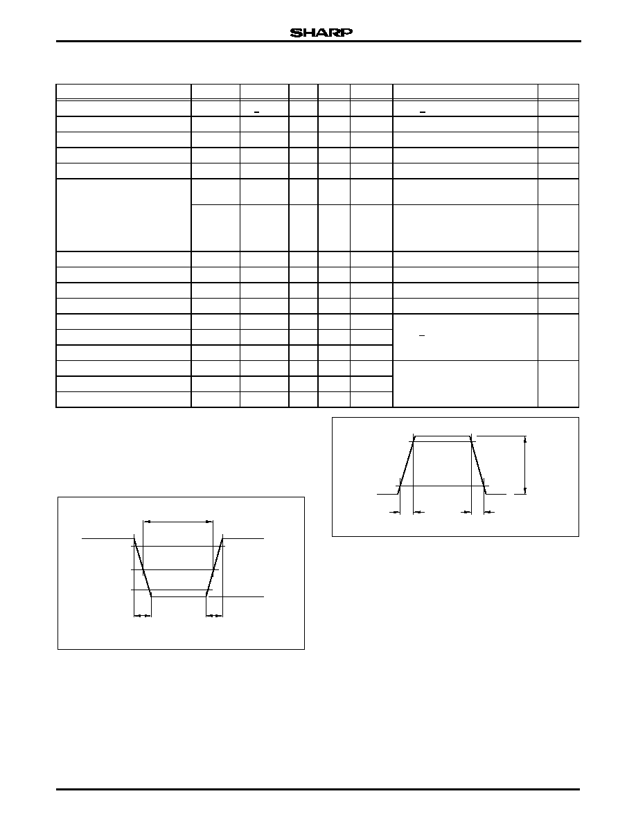
Figure 2. GP2W0110YPS/GP2W0114YPS
Infrared Transceiver Module Output Waveform
V
OL
V
OH
90%
V
OH
50%
10%
CRITERIA FOR
PULSE POSITION
V
OL
t
F
t
R
t
W
GP2W0110YPS-2
Figure 3. Standard Optical System
t
R
t
F
I
E
GP2W0110YPS-16