 | –≠–ª–µ–∫—Ç—Ä–æ–Ω–Ω—ã–π –∫–æ–º–ø–æ–Ω–µ–Ω—Ç: LT0H34P | –°–∫–∞—á–∞—Ç—å:  PDF PDF  ZIP ZIP |

Hologram Laser(3 beam) for MD players/recorders
TEC940525
LT0H34P
s
Features
s
Applications
(1) MD players/recorders
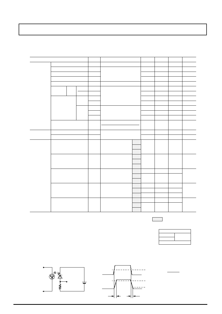
(Unit: mm)
s
Outline Dimensions
HOLOGRAM LASER
s
Absolute Maximum Ratings
Parameter
Symbol
Ratings
Units
Optical power output *1
P
H
32
mW
Laser
2
Reverse
voltage
V
R
30
V
15
Operating temperature *2
Topr
-10 to +60
∞C
Storage temperature *2
Tstg
-40 to +85
∞C
Tsol
∞C
(2) Enables to design compact pick-up thanks to
compact package. (Thickness; 4.8mm)
G
D1
D2
D3
D4
D5
3
4
6
8
7
1
10
9: NC
5
2
LT0H34P
7
6
4.6
1.2
2.0
1.27
Hologram grass
4
9
5
1
3
10
8.2
6.63
3.2
0.25
10 -
0.4
MIN.
0.25
MIN.
8.2
4.77
4.8
2.8
0.3
MAX.
4.8
3.97
4.9
8
2
P1.4
0.2 X 3 = 4.2
±
±
0.2
Monitor PD
*2 Case temperature
*3 At the position of 1.6mm from the
bottom face of resin package.
*1 Output power from hologram laser
Monitor photodiode
Photodiode for signal detection
Soldering temperature *3
260(5s or less)
(Notice)
(Internet)
∑ Data for Sharp's optoelectronic/power devices is provided for internet. ( Address http://www.sharp.co.jp/ecg/)
∑ In the absence of device specification sheets, SHARP takes no responsibility for any defects that may occur in equipment using any SHARP devices
shown in catalogs, data books, etc. Contact SHARP in order to obtain the latest device specification sheets before using any SHARP device.
∑ Specifications are subject to change without notice for improvement.
(1) Compact package with high power output
(MAX. 35mW)
Cap glass
0.25
LD chip
Reference surface
Laser diode
[Terminal connection]
(3) Since its semiconductor laser, signal detection
photocell, and circuit array are assembled in a
package, the optical pick is simple in assembling
and adjustment
(4) The adjustment during pickup assembly is eased
and can easily be automated.
TEC940525
LT0H34P
*6 Measuring method is shown below.
*1 Output power form LD chip
*2 Oscillation mode: TEM
00
*5 Ev:Illuminance by CIE standard light source A(tungsten lamp)
s
Electro-optical Characteristics
(Tc=25∞C)
Parameter
Symbol
Condition
Units
Threshold current
Ith
-
-
60
80
mA
Operating current
Iop
-
125
150
mA
Operating voltage
Vop
P
H
=27.4mW *1
-
1.8
2.2
V
Wavelength *2
p
770
785
800
nm
Monitor current
Im
P
H
=27.4mW *1,V
R
=5V
-
0.14
-
mA
-
11
-
-
26
-
-
-
±1
-
-
±3
∞
-
-
±30
µ
m
-
-
-
±30
µ
m
-
-
±80
µ
m
18.3mW
0.25
0.5
0.85
mW/mA
Iop(27.4mW) - Iop(9.1mW)
Dark current
-
-
150
nA
Terminal capacitance
Ct
-
20
-
pF
Reverse voltage
V
R
I
R
=10
µ
A
15
-
-
V
Dark current
I
d
-
-
10
nA
1.0
-
8
Terminal capacitance
Ct
V
R
=1.5V,f=1MHz
pF
0.6
-
6
120
210
-
Short circuit current *3 *4
Isc
Ev=1000Lx
40
80
-
nA
60
115
-
-
-
660
Response time *5
V
R
=1.5V, R
L
=180
ns
-
-
660
A
B
C
A
B
C
A
B
C
A
B
C
A
B
C
MIN
TYP
MAX
Laser diode
=780nm
R
L
=180
Input
Output
V
R
=1.5V
Input
Output
95%
5%
t
r
t
f
50%
Radiation
Characteristics
Angle
Parallel
Perpen-
dicular
//
//
x
y
z
Differentioal efficiency
Emission
Point
accuracy
∞
∞
∞
V
R
=5V
V
R
=1.5V
I
d
t
r
,t
f
P
H
=27.4mW *1
D1,D5 ∑∑∑∑∑∑∑ A
D2,D3 ∑∑∑∑∑∑∑ B
Segment No.
D4 ∑∑∑∑∑∑∑∑∑∑∑ C
*7 Applicabledivisions
correspond to pattern segment No.
D2
D3
D4
D5
D1
Fig.1
Angle
Positon
Monitor
Photodiode
Laser
for signal
detection
Photodiode
*3 Values in each element. Elements other than subject elemens shall be
measured while the anode and the cathode are short-sircuited to each other
*4 Short-circuit currents between segments D1 and D5 or D3 and D4 shall be
within ±10% of the average
TEC S 940101
a
b
GND
*3
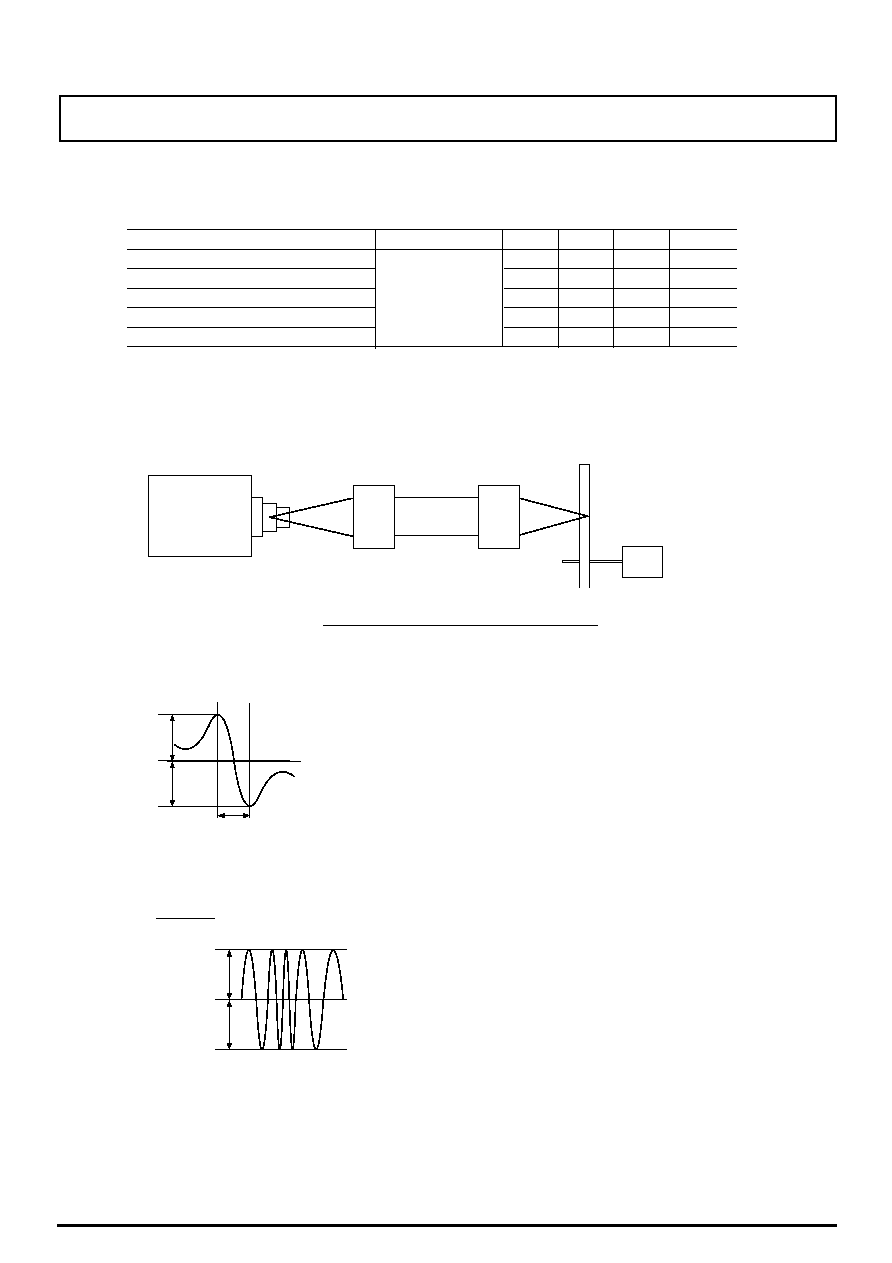
*1 Measuring method is shown below.
Measuring method of electro-optical characteristics
Laser
Driver
APC
HL
C.L.
NA=0.17
f=10.74mm
NA=0.45
f=3.4mm
Disk
TCD-782
(A-BEX)
(Tc=25∞C)
Parameter
Condition
MIN
TYP
MAX
Units
Focus error signal offsetting *2
-0.4
0
+0.4
µ
m
Lead-in for focus error signal *3
10
19
30
µ
m
RF Output amplitude (D2+D3+D4)*4
5
10
-
µ
A p-p
RES Output amplitude (D1-D5) *5
0.3
0.55
1.0
Radial error balance *6
-20
-
20
%
s
Electro-optical Characteristics *1
µ
A p-p
*2 Distance between FES=0 and jitter Min. point
*4 Focus/radial servo is ON-state
*5 RES output amplitude: under the condition that only focus servo is effected
Factors *2 to *6 are measured with high-reflection disk
(TCD782 made by A-BEX) at 3
µ
Ap-p of FES output amplitude
3
µ
Ap-p of the FES output amplitude is set through focusing oscillation
FES
RES
D1,D2,D3,D4,D5: Refer to pattern segment No. (Fig.1)
a
b
c
LT0H34P
Values at
FES output amplitude
5
µ
Ap-p
Sharp's
Actuator
*6 (a - b) / 2
a + b