CD-ROM drives
Parameter
Ratings
Unit
*1 Optical power output
4.3
mW
Reverse
voltage
Laser
2
Monitor photodiode
V
R
30
V
OPIC supply voltage
V
CC
6
Topr
-10 to +70
Tstg
-40 to +85
�C
Tsol
260(5s or less)
Symbol
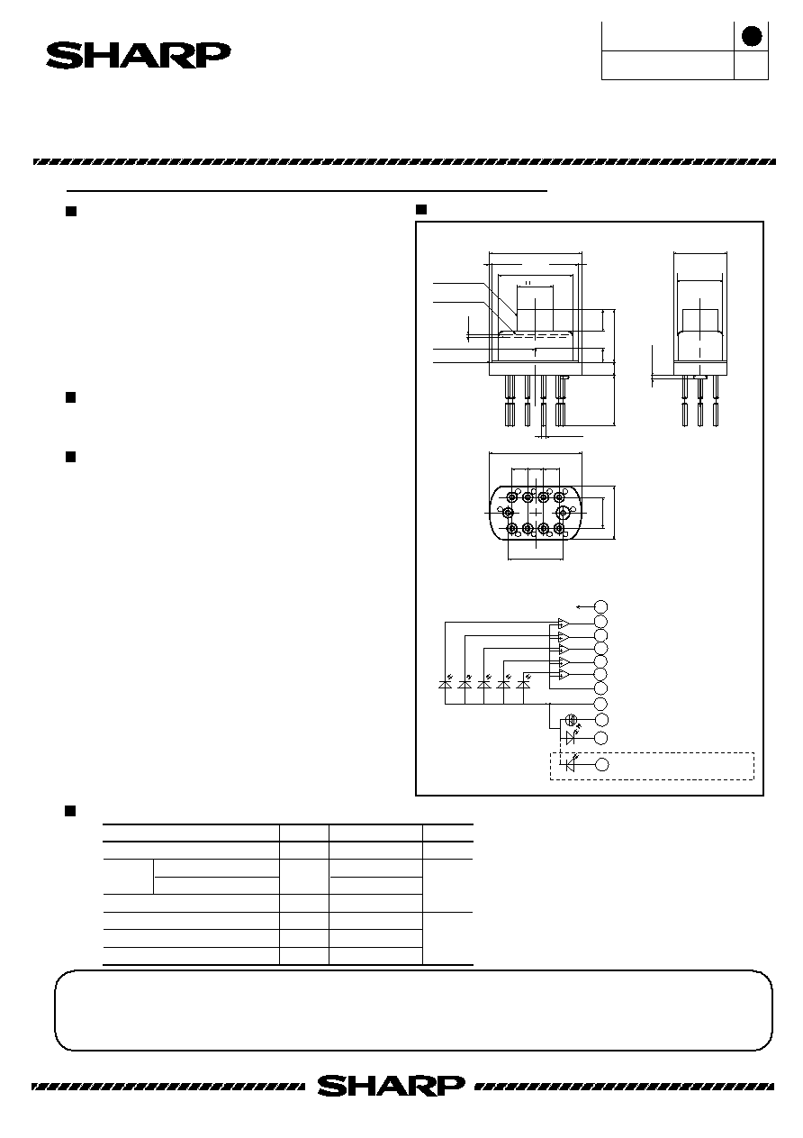
[Terminal connection]
D3
Vcc
LD
GND
V
A
V
B
V
C
V
E
V
F
1/2Vcc
D4 D1
D2
D5
Monitor PD
Monitor PD
1
4
6
2
3
7
9
5
10
8
1
7
6
4.6
1.2
2.0
1.27
Hologram glass
Cap glass
0.25
LD chip
Reference surface
4
9
5
1
3
10
�8.2
�
6.63
3.2
0.25
MIN.
0.25
MIN.
�
8.2
4.77
4.8
2.8
0.3
MAX.
4.8
3.97
4.9
8
2
(Tc=25�C)
H
P
LT0H49L/T
Compact Hologram Laser
(LT0H49L)
(LT0H49T)
(Unit:mm)
10
-�
0.4
Compact Hologram Laser(3-beam) for 16X Speed CD-ROM Drive
P1.4X3=4.2
Tec.970101
Under development
New product
Features
(1) Built-in high speed(TYP.30MHz) OPIC* for 16X
speed CD-ROM drive
(2) Enables to design compact pick-up thanks to
compact package (Thickness: 4.8mm)
(3) Voltage output type
(Needless of external noise solution)
(4) Low current operation type
(Operating current : TYP. 36mA)
Applications
Model Name
� LT0H49L----Single power supply
� LT0H49T----Dual power supply
*OPIC: OPIC (Optical IC) is a trademark of the SHARP Corporation.
An OPIC consists of a light-detecting element and signal-processing circuit
integrated onto a single chip.
Model Name
*2 Operating temperature
*2 Storage temperature
*3 Soldering temperature
*1 Output power from hologram laser
*2 Case temperature
*3 At the position of 1.6mm from the
bottom face of resin package
(Notice)
(Internet)
� Data for Sharp's optoelectronic/power devices is provided for internet. ( Address http://www.sharp.co.jp/ecg/)
� In the absence of device specification sheets, SHARP takes no responsibility for any defects that may occur in equipment using any SHARP d
shown in catalogs, data books, etc. Contact SHARP in order to obtain the latest device specification sheets before using any SHARP dev
� Specifications are subject to change without notice for improvement.
As of January 1997
Outline Dimensions
Parameter
Symbol
Conditions
Unit
Remarks*1
Threshold current
Ith
-
-
25
mA
Operating current
Iop
-
36
45
mA
Laser
Operating voltage
Vop
P =2.7mW
H
-
1.75
2.2
V
Wavelength
p
770
780
795
nm
Monitor current
Im
0.06 0.28
0.50
0.12 0.55
1.00
mA
x
- 80
-
80
m
Emission point
Accuracy(position)
y
-
-
80
m
z
-
80
m
1.8mW
Differential efficiency
0.17
0.27
0.55 mW/mA
Sensitivity(*)
S
-
0.10
-
mA/mW
Dark current
I
D
V
R
=15V
-
-
150
nA
Terminal capacitance Ct
-
9
-
pF
Operating supply voltage Vcc
4.5
-
5.5
V
Collector current
Icc
Vcc=5V
2.0
4.5
9.0
mA
V
OD
Difference from Vcc/2
-25
0
25
mV
V
A~F
Extremes of off-set voltage
V
OD
Vcc=5V, No light
-15
0
15
mV
Response frequency*2
fc
Vcc=5V,-3dB
-
MH
Z
V
E
,V
F
MIN.
TYP. MAX.
V
A
-V
B
,V
E
-V
F
39
- 80
- 80
V
A
,V
B
,V
C
fc
Vcc=5V,-3dB (*3)
24.0
30.0
2.0
1.0
-
MH
Z
R
Iop(2.7mW)-Iop(0.9mW)
*3 f
CF=
(fc(V
A
)+f
c
(V
B
)+2f
C
(V
C
))/4
P
H
=2.7mW, V
R
=15V
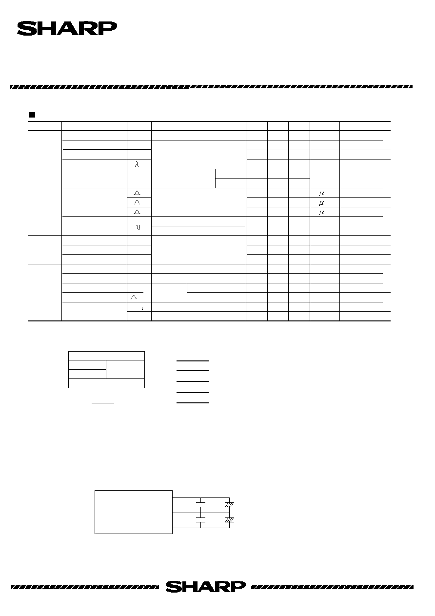
LT0H49L
LT0H49T
Vcc
GND
0.022�F
0.022�F
10�F
10�F
1/2Vcc
[Ex.]
+
-
+
-
Tec.970101
LT0H49L/T
Electro-optical Characteristics
(Vcc=5V, Tc=25�C)
Monitor
photodiode
OPIC for
signal
detection
Output off-set voltage
D 2
D 3
D 4
D 5
D 1
D 1
V
E
D 2
V
A
D 4
V
C
D 5
V
F
D 3
V
B
Terminal No.
Fig.1
* Sensitivity for output power from hologram laser
*1 Applicable divisions correspond to pattern segment No.
Hologram
laser
*2 Output amplitude = 0dB(input signal 100MHz)
Note)Please attach bypass capacitor at the position of 1cm or less from pins (between Vcc and GND, GND and 1/2Vcc).
As of January 1997
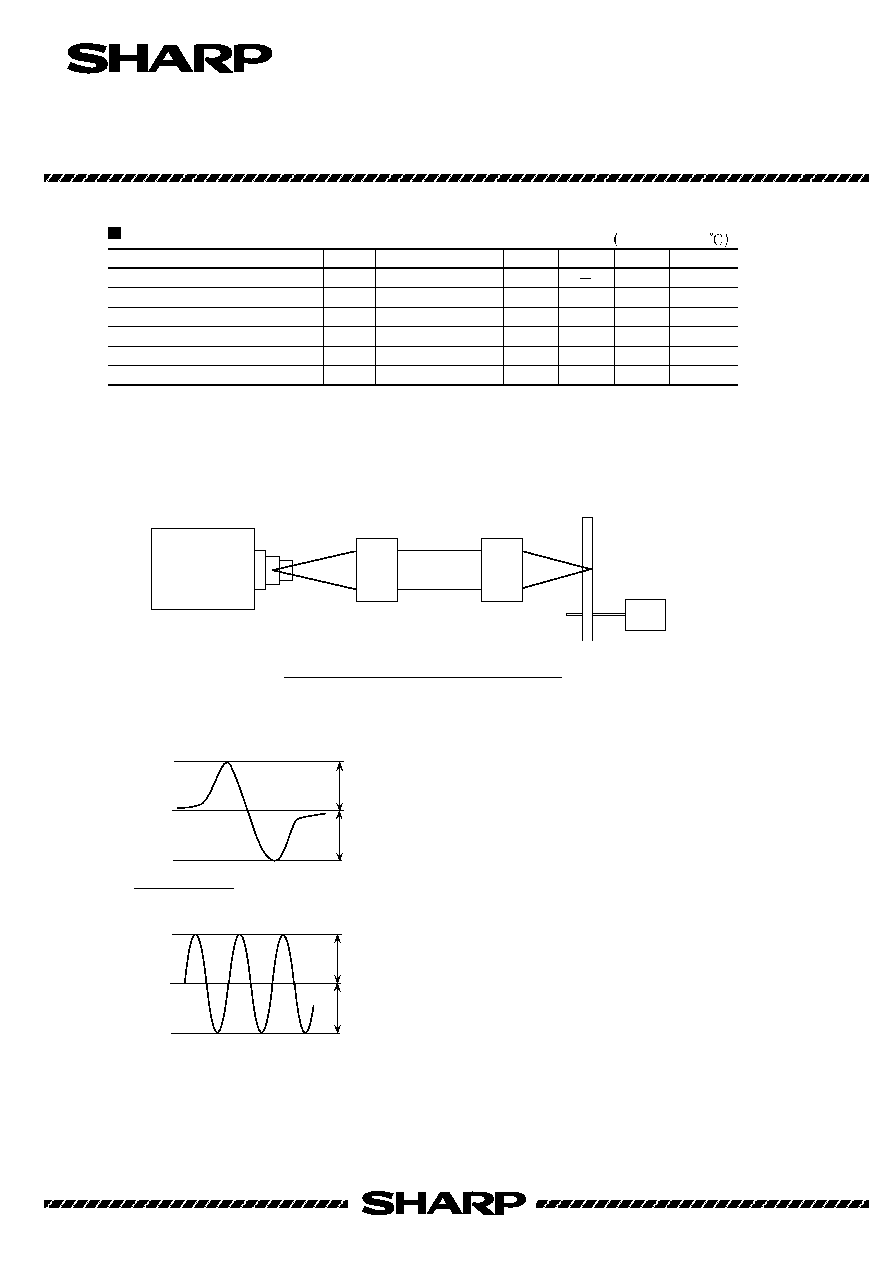
Measuring method of electro-optical characteristics
Laser
Driver
HL
C.L
NA=0.11
f=20.6mm
Actuator
NA=0.50
f=4.5mm
Disk
(SONY:YEDS-18)
Vcc=5V,Tc=25
Focus error balance*3
20
%
RF output amplitude*5
V
RF
V
RF
=0.55V
V
RF
=0.55V
V
RF
=0.55V
V
RF
=0.55V
0.38
0.9
V p-p
Focus error signal output amplitude*6
0.23
0.35
0.47
0.08
0.12
0.16
V p-p
V p-p
20
Radial error balance*4
20
%
P
O
=3.0mW
P
O
=3.0mW
20
Parameter
Symbol
Condition
MIN.
TYP.
MAX.
Unit
Focus error signal offsetting*2
0.5
� m
0.5
a
b
GND
*4
( + amplitude of RES )
( - amplitude of RES )
APC
A
B
( + amplitude of FES)
( - amplitude of FES)
*3 (a - b) / (a + b)
Tec.970101
LT0H49L/T
Electro-optical Characteristics*1
Radial error signal output amplitude
*1 Measuring method is shown below.
V
A
,V
B
,V
E
,V
F
: Refer to pattern segment No.(Fig.1).
*2 Distance between FES=0 and jitter Min. point
( a - b )
2 X ( a + b )
*5 Amplitude of V
A
+ V
B
+ 2V
C
, focus/radial servo is ON-state.
*6 V
B
-V
A
at focus rocking condition
*7 V
E
-V
F
under the condition that only focus servo is effected.
As of January 1997