In the absence of confirmation by device specification sheets, SHARP takes no responsibility for any defects that may occur in equipment using any SHARP devices
shown in catalogs, data books, etc. Contact SHARP in order to obtain the latest device spcification sheets before using any SHARP device.
Hall IC
s
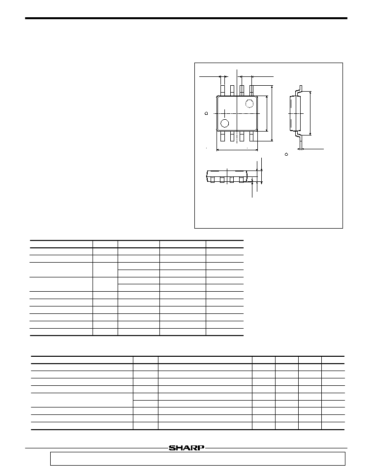
Outline Dimensions
(Unit : mm)
LT202A
GaAs Hall IC for Fan Motor
s
Features
°Increasing the efficiency of motor rotation due to cutting
the electric current which doesn't contributing to rotation
°Combining a GaAs Hall device and a driver IC in a
compact 8-pin SOP package
°Operation in low magnetic flux density (10mT) due to
applied high sensitive Hall device
°Built-in protection circuit, alarm output and automatic
restart circuit
s
Applications
°Brushless fan motors
1. Cooling fan motors for personal computers, word
processors, etc.
2. Directly cooling fan motors for cooling fin, PCB, etc.
3. Fan motors for air circulation of temperature sensor in
air conditioner
LT202A
As for dimensions of tape-packaged
products, refer to page 44 .
s
Absolute Maximum Ratings
(T
a
=25∞C)
Supply voltage
Output voltage
Output current (peak)
Output current (continuous)
Coil input voltage
Alarm output sink current
Power dissipation
Oparating temperature
Storage temperature
Symbol
V
CC
V
O
I
OMAX
I
O
V
IN
I
SINK
P
D
T
opr
T
stg
Conditions
V
CC
=12V
V
CC
=24V
V
CC
=12V
V
CC
=24V
Rating
30
55
750
450
250
150
-0.2 to 0.2
5
400
-20 to +80
-55 to +150
Unit
V
V
mA
mA
mA
mA
V
mA
mW
∞C
∞C
Parameter
Soldering temperature
*1
T
sol
260
∞C
*1 Soldering time : within 10 seconds
(Note) Unspecified condition is Vcc=24V.
* In case of oscillating from power supply due to wiring, connect a condenser between 8-pin (Vcc) and 4-pin (GND).
s
Electrical Characteristics
(T
a
=25∞C)
Output saturation voltage
Output cut-off current
Operating supply voltage
Supply current
Operating magnetic flux density
Coil input sensitivity
Alarm output saturation voltage
Alarm output leakage current
Symbol
V
OUT
I
OC
V
CC
I
CC
B
1
B
2
V
IN
V
SAT
I
LEAK
Conditions
I
O
=250mA, V
CC
=12V
V
O
=55V
*
At no-load
I
SINK
=4mA
V=28V
MIN.
-
-
8
-
-10
-
15
-
-
TYP.
-
-
-
-
-
-
-
-
-
MAX.
1.5
30
28
13
-
10
-
0.5
15
Unit
V
µ
A
V
mA
mT
mT
mV
V
µ
A
Parameter
0.1±0.1
0.65
0.60
1.25±0.2
X direction : against package
center -1.4±0.2a
Y direction : against package
center 0.0±0.2a
Z direction : from package
surface 0.0±0.2a
The section of leads (both sides of package in X-direction) is connected with the terminal of
internal IC. Be careful in connecting other circuits.
Terminal connection
1:Input terminal for phase detection
2:Input terminal for phase detection
3:Condenser terminal for rotation detection
4:GND
5:Alarm output
6:Vout
7:Vout
8:Vcc
-
Sensor
positioning
Y
X
0
1
4
8
5
8-0.4±0.1
5.0±0.2
0.15±0.05
4.4±0.2
6.5±0.4
(5.05)
P 1.27TYP
-

s
Block Diagram and Timing Chart
Fig. 1 Output Saturation Voltage vs.
Ambient Temperature
Fig. 2 Output Saturation Voltage vs.
Input Current (Continuous)
Hall IC
LT202A
V
CC
Motor
8
7
6
Constant voltage
5
4
3
GND Alarm output
Phase
detection coil
1
2
+
-
+
-
+
-
Magnetic pole
S (>10mT)
S (>10mT)
N
(<-10mT)
N(<-10mT)
Coil input(1:+)
V
1
-V
2
=<0
V
1
-V
2
>15mV
V
1
-V
2
<-15mV
V
1
-V
2
>=0
OUT 6
OFF
OFF
OFF
ON
OUT 7
ON
OFF
OFF
OFF
Timing chart
Rotation detector/
automatic restart circuit
V
CC
=12V
I
O
=250mA
0
-40
80
60
20
0
-20
40
100
2.0
1.6
1.2
0.8
0.4
1.8
1.4
1.0
0.6
0.2
Output saturation voltage V
OUT
(V)
Ambient temperature T
a
(∞C)
V
CC
=12V
T
a
=25∞C
0
0
200
100
300
2.0
1.6
1.2
0.8
0.4
1.8
1.4
1.0
0.6
0.2
Output saturation voltage V
OUT
(V)
Input current(Continuous) I
O
(mA)
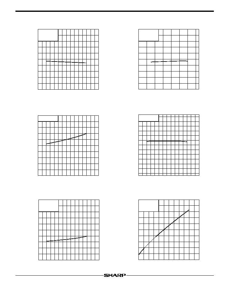
Fig. 3 Supply Current vs. Ambient
Temperature
Fig. 4 Supply Current vs. Supply
Voltage
Fig. 8 Alarm Output Saturation Voltage vs.
Alarm Output Sink Current
Fig. 7 Alarm Output Saturation Voltage
vs. Ambient Temperature
Fig. 5 Coil Input Sensitivity vs. Ambient
Temperature
Fig. 6 Operating Magnetic Flux Density
vs. Ambient Temperature
Hall IC
LT202A
V
CC
=24V
I
SINK
=4mA
0
-40
80
60
20
0
-20
40
100
0.20
0.16
0.12
0.08
0.04
0.18
0.14
0.10
0.06
0.02
Alarm output saturation voltage V
SAT
(V)
Ambient temperature T
a
(∞C)
V
CC
=12V
T
a
=25∞C
0
0
4
2
1
6
3
5
0.10
0.08
0.06
0.04
0.02
Alarm output saturation voltage V
SAT
(V)
Alarm output sink current I
SINK
(mA)
V
CC
=24V
-12
-40
80
60
20
0
-20
40
100
12
6
2
-4
-8
10
8
4
0
-2
-6
-10
Operating magnetic flux density B
2
(mT)
Ambient temperature T
a
(∞C)
V
CC
=24V
0
-40
80
60
20
0
-20
40
100
20
16
12
8
4
18
14
10
6
2
Coil input sensitivity V
IN
(mV)
Ambient temperature T
a
(∞C)
V
CC
=12V
At no
-
load
0
-40
80
60
20
0
-20
40
100
20
16
12
8
4
18
14
10
6
2
Supply current I
CC
(mA)
Ambient temperature T
a
(∞C)
T
a
=25∞C
At no-load
0
0
25
30
5
10
15
20
35
20
16
12
8
4
18
14
10
6
2
Supply current I
CC
(mA)
Supply voltage V
CC
(V)