 | –≠–ª–µ–∫—Ç—Ä–æ–Ω–Ω—ã–π –∫–æ–º–ø–æ–Ω–µ–Ω—Ç: LT5038T | –°–∫–∞—á–∞—Ç—å:  PDF PDF  ZIP ZIP |
Dot Matrix LED
152
(Notice)
°
In the absence of confirmation by device specification sheets, SHARP takes no responsibility for any defects that may occur in equipment using any SHARP
devices shown in catalogs, data books, etc. Contact SHARP in order to obtain the latest device specification sheets before using any SHARP device.
(Internet)
°
Data for sharp's optoelectronic/power device is provided for internet.(Address http://www.sharp.co.jp/ecg/)
s
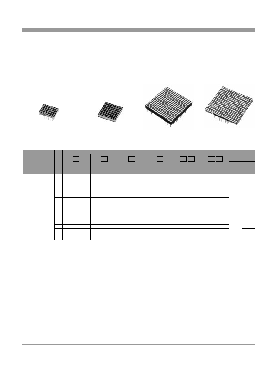
General Description
Sharp's dot matrix LEDs can express characters and symbols on a display.
(Number of dots: 5!7, 8!8, 16!16). We can supply wide color variation;
high-luminosity red T series, yellow-green E series, sunset orange S series,
dichromatic emission, etc.
s
Dot Matrix LED
*1
Common pins show row.(Column row)
LT5038T
LT5037T
LT5010T
LT5010D
LT5105D
LT5106D
LT5008D
LT5014D
LT5005D
LT5106S
LT5014S
LT5005S
LT5106E
LT5105E
LT5014E
LT5008E
LT5005E
LT5040ET
LT5050ET
LT5008ED
LT5007ED
LT5027ED
LT5017ED
LT5016ED
LT5026ED
LT5013T
LT5005T
Number of dots
*1
Common pins
Outline
dimensions
(mm)
Red
(High-luminosity)
T
Outline dimensions
Radiation color
Page
Figure
K
12.7!17.8
5!7
8!8
16!16
20!20
40!40
64!64
96!96
30.2!30.2
31.8!31.8
31.9!31.9
A
K
2
3
1
4
5
5/6
7
8
9
10
11
12
K
A
K
A
K
A
K
A
A
K
A
A
A
A
Red
(High-luminosity)
T
Sunset orange
S
Red
D
D
Yellow-green
E
Yellow
green
E
Yellow-green+
E
+ Red
LT5038T
LT5017ED
LT5040ET
LT5016ED
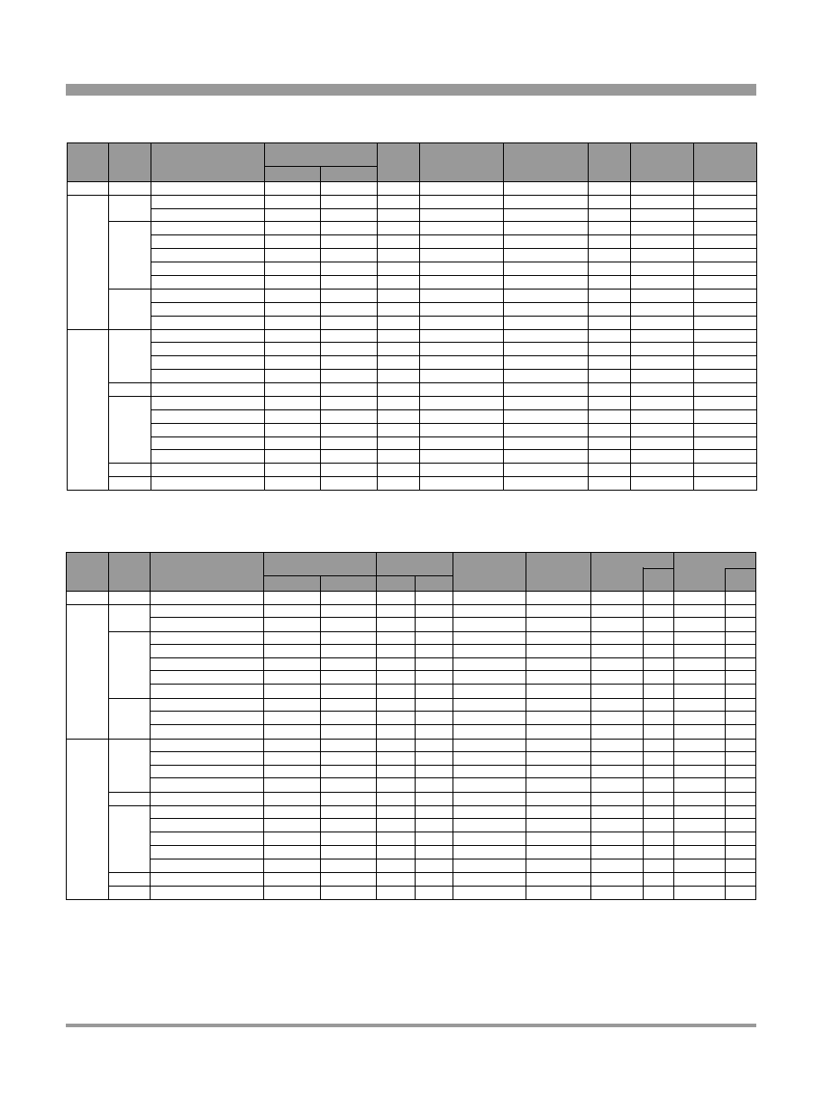
*1 Common pins show row.(Column row) *2 Duty ratio=1/10, Pulse width=0.1ms
*3 Duty ratio=1/16, pulse width=0.1ms
LT5026ED
LT5037T
LT5010T
LT5010D
LT5106D
LT5106S
LT5106E
LT5008ED
LT5105D
LT5105E
LT5007ED
LT5008D
LT5008E
LT5014D
LT5014S
LT5014E
LT5005D
LT5005S
LT5005E
LT5040ET
LT5005T
LT5013T
LT5050ET
LT5016ED
LT5027ED
LT5038T
LT5017ED
Number
of dots
Radiation color
Model No.
15
5
-20 to +60
-20 to +80
-20 to +80
-20 to +80
-20 to +70
-20 to +80
-20 to +80
-20 to +80
-20 to +80
-20 to +80
-20 to +80
-20 to +80
-20 to +80
-20 to +80
-20 to +80
-20 to +80
-20 to +80
-20 to +80
-20 to +80
-20 to +80
-20 to +80
-20 to +80
-20 to +80
-20 to +80
-20 to +60
-20 to +60
-20 to +60
-20 to +60
-20 to +70
-20 to +70
-20 to +60
-20 to +60
-20 to +60
-20 to +60
-20 to +60
-20 to +60
-20 to +60
-20 to +60
-20 to +60
-20 to +60
-20 to +60
-20 to +60
-20 to +60
-20 to +60
-20 to +60
-20 to +60
5
5
5
5
5
5
5
5
5
5
5
5
5
5
5
5
5
5
5/5
5
5
5
1.45
0.91
0.91
0.91
0.91
0.91
0.91
0.91
0.91
0.91
0.91
1.45
1.45
1.45
1.45
1.45
1.45
1.45
1.45
1.45/1.45
1.45
1.45
1.45
50
*2
Anode common*
1
Cathode common*
1
50
*2
50
*2
50
*2
50
*2
50
*2
50
*2
50
*2
50
*2
50
*2
50
*2
80
*3
80
*3
80
*3
80
*3
50
*2
80
*3
80
*3
80
*3
50/50
*3
80
*3
80
*3
80
*3
15
15
15
15
20
20
20
15
15
15
15
15
15
15
15
15
15
15
15/15
15
15
15
12.7!17.8
5!7
8!8
16!16
20!20
40!40
64!64
96!96
30.2!30.2
31.9!31.9
31.7!31.7
31.8!31.8
Yellow-green/Red
Yellow-green/Red
Yellow-green/Red
Red(High-luminosity)
Red(High-luminosity)
Red
Red
Yellow-green
Yellow-green
Yellow-green
Sunset orange
Red
Red
Red(High-luminosity)
Sunset orange
Sunset orange
Yellow-green/Red(High-luminosity)
Yellow-green/Red(High-luminosity)
Red
Yellow-green
Yellow-green/Red
Yellow-green/Red
Red(High-luminosity)
(Ta=25∞C)
Forward current
I
F
(mA)
Outline
dimensions
(mm)
Peak forward current
I
FM
(mA)
Derating factor
(mA/∞C)
Pulse
Reverse voltage
V
R
(V)
Operating temperature
T
opr.
(∞C)
Storage temperature
T
stg.
(∞C)
s
Absolute Maximum Ratings
Figures shown below are values per dot.
* Each figure shown in the table is yellow-green/red. *1 Common pins show row.(Column row) *2 I
FM
=50mA *3 I
F
=10mA
LT5026ED
LT5037T
LT5010T
LT5010D
LT5106D
LT5106S
LT5106E
LT5008ED
LT5105D
LT5105E
LT5007ED
LT5008D
LT5008E
LT5014D
LT5014S
LT5014E
LT5005D
LT5005S
LT5005E
LT5040ET
LT5005T
LT5013T
LT5050ET
LT5016ED
LT5027ED
LT5038T
LT5017ED
2.4/2.2
2.4/2.2
1.85
1.85
3.0
(4.5)
660
20
50
100
4
4
4
4
4
4
4
4
4
4
4
4
4
4
4
3
4
4
4
4
3
4
4
10
10
10
10
10
10
10
10
10
10
10
10
10
10
100
10
10
10
10
100
10
10
50
50
50
50
10
10
10
50
50
50
50
35
50
50
50
50
50
50
50
10
50
50
30/35
30/35
20
35
35
35
30
30/35
35
30
20
50
35
30
30/20
20
35
35
30
30/20
30/35
30/35
565/635
565/635
660
635
635
610
565
565/635
635
565
660
635
610
565
565/660
660
635
610
565
565/660
565/635
565/635
1.9/1.6
2.5/2.0
2.2
1.11
1.11
1.11
1.69
2.08/1.56
2.03
2.7
1.35
1.3
1.11
1.7
1.45/1.70
1.78
1.04
1.11
1.3
(1.9)/(3.0)
5.2/3.9
7.15/5.85
3.0
3.0
2.3
2.7
2.7
2.7
2.7
3.0/2.7
3.0
3.0
3.0
3.0
3.0
3.0
3.0
3.0
2.7
2.7
3.0
3.0
3.0
3.0
2.2
2.2
2.2
2.4
2.2
2.4
1.85
2.2
2.2
2.4
1.85
2.2
2.2
2.4
2.4/2.2
2.4/1.85
2.4/1.85
2.4/2.2
2.4/2.2
12.7!17.8
5!7
8!8
16!16
20!20
40!40
64!64
96!96
30.2!30.2
31.8!31.8
31.9!31.9
31.7!31.7
Luminous intensity
*3
I
V
(mcd)
TYP.
TYP.
MAX.
Forward voltage
*2
V
F
(V)
Peak emission wavelength
p
(nm)
TYP.
Spectrum radiation bandwidth
(nm)
TYP.
I
F
(mA)
V
R
(V)
Reverse current
I
R
(
µ
A)
MAX.
(Ta=25∞C)
*
*
*
*
*
*
*
Number
of dots
Radiation color
Model No.
Anode common*
1
Cathode common*
1
Outline
dimensions
(mm)
Yellow-green/Red
Yellow-green/Red
Yellow-green/Red
Red(High-luminosity)
Red(High-luminosity)
Red
Red
Yellow-green
Yellow-green
Yellow-green
Sunset orange
Red
Red
Red(High-luminosity)
Sunset orange
Sunset orange
Yellow-green/Red(High-luminosity)
Yellow-green/Red(High-luminosity)
Red
Yellow-green
Yellow-green/Red
Yellow-green/Red
Red(High-luminosity)
s
Electro-optical Characteristics
Figures shown below are values per dot.
Dot Matrix LED
153
(Notice)
°
In the absence of confirmation by device specification sheets, SHARP takes no responsibility for any defects that may occur in equipment using any SHARP
devices shown in catalogs, data books, etc. Contact SHARP in order to obtain the latest device specification sheets before using any SHARP device.
(Internet)
°
Data for sharp's optoelectronic/power device is provided for internet.(Address http://www.sharp.co.jp/ecg/)
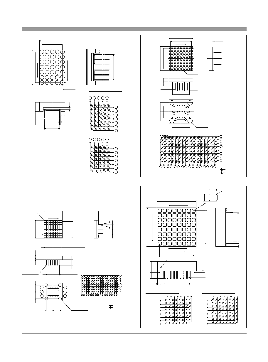
Dot Matrix LED
Outline Dimensions(Unit:mm)
154
(Notice)
°
In the absence of confirmation by device specification sheets, SHARP takes no responsibility for any defects that may occur in equipment using any SHARP
devices shown in catalogs, data books, etc. Contact SHARP in order to obtain the latest device specification sheets before using any SHARP device.
(Internet)
°
Data for sharp's optoelectronic/power device is provided for internet.(Address http://www.sharp.co.jp/ecg/)
P2.54
!
6=15.24
P2.54
!
4=10.16
12.7
±
0.3
17.78
±
0.4
35-¯2.0
P2.54
!
5=12.7
6.6
4.6
7.62
1.0
2.0
0.45
12-¯
+0.15
-0
2.0
6
5
4
9
2
11
12
8
7
10
3
1
Internal connection diagram
LT5037T
6
5
4
9
2
11
12
8
7
10
3
1
LT5038T
P
I
N
1
6
P
I
N
12
7
24-¯0.45
7.5
7.5
7.5
7.5
4-¯4.0MAX
0.4MAX
Calking
Calking
20
Column
1
1
8
17
24
8
5
6
13
Row
5
B
8
1
64-
t
1.9
P2.5
!
7=17.5
P2.0
!
7=14
P2.5
!
7=17.5
+0
-0.4
20
+0
-0.4
9
10
Internal connection diagram
11
12
13
14
15
16
1
17
2
18
3
19
4
20
21
5
22
6
23
7
24
8
Row 1
Row 2
Row 3
Row 4
Row 5
Row 6
Row 7
Row 8
Column 1
Column 2
Column 3
Column 4
Column 5
Column 6
Column 7
Column 8
I Do t
Red
Yellow-green
16
9
P2.5
!
7=17.5
20.0
+0
-0.4
Column
1
8
P2.5
!
7=17.5
20.0
+0 -0.4
Row
81
64- 1.8
¯
0.4
1.0
3.0
P2.0
!
7=14.0
6.0
+1.0 -0.5
0.45
¯
24-
5.0
5.0
7.5
7.5
7.5
7.5
4-
¯4.0
MAX.
Calking
MAX.
Calking
9
10
Internal connection diagram
11
12
13
14
15
16
1
17
2
18
3
19
4
20
21
5
22
6
23
7
24
8
Row 1
Row 2
Row 3
Row 4
Row 5
Row 6
Row 7
Row 8
Column 1
Column 2
Column 3
Column 4
Column 5
Column 6
Column 7
Column 8
I Do t
9
1
17
16
8
24
Red
Yellow-green
16-¯0.45
Column1
Column8
18
12
10
13
14
5
4
1
3
12
10
13
14
5
4
1
3
2 17 15 6
8 11 9
18 2 17 15 6
8 11 9
Row1
PIN.18
PIN.1
9
10
2.7
4-C0.4
(For all 64 pcs.)
2.7
Row8
3.81
!
7=26.67
2.54
!
8=20.32
3.81
!
7=26.67
22.86
0.05
8.0
1.0
4.5
1.95
0.05
1.95
30.2
±
0.2
30.2
±
0.2
Internal connection diagram
Internal connection diagram
LT5105
t
Series
LT5010
t
Series/LT5106
t
Series
Dot shows PIN1
LT5037T/LT5038T
LT5017ED
1
2
3
4
LT5027ED
LT5010
t
Series LT5105
t
Series/LT5106
t
Series

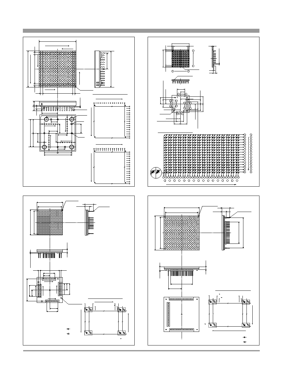
Dot Matrix LED
Outline Dimensions(Unit:mm)
16-¯0.55
Direction of Pin1
64
-¯
3.
0
4-
¯1
.5
4.0
!
7=28.0
3.0
1.0
6.0
2.0
8.0
1
8
16
9
24.0
2
4
.
0
1
6
.
0
2.54
!
7=17.78
4
.
0
!
7
=
2
8
.
0
31.8
±
0.2
3
1
.
8
±
0
.
2
11 Row 1
9 Row 2
12 Row 3
13 Row 4
5 Row 5
4 Row 6
1 Row 7
3 Row 8
16
2
6
7
8
15
14
10
C
O
L
U
M
N
1
C
O
L
U
M
N
2
C
O
L
U
M
N
3
C
O
L
U
M
N
4
C
O
L
U
M
N
5
C
O
L
U
M
N
6
C
O
L
U
M
N
7
C
O
L
U
M
N
8
LT5008D
Internal connection diagram
256-¯1.4
1.95
7.5
2
.
0
2
.
5
1
.
0
8
.
0
8
.
0
1
4
.
0
1
4
.
0
1.0
2
.
0
2
.
0
2
.
0
2.0
12.0
12.0
1
0
.
0
1
0
.
0
1
0
.
0
1
0
.
0
1.95
1
.
9
5
1
.
9
5
4-¯
3.0
2
.
0
!
1
3
=
2
6
.
0
2.0
!
13=26.0
2.0
!
7=14.0
1
8
9
16
32
25
24
17
31.9
±
0.2
3
1
.
9
±
0
.
2
Column1
Internal connection diagram
LT5013T
LT5014
t
Column16
Column1
Column16
30
18
32
28
20
26
22
25
9
6
10
4
12
16
2
14
Row1
Row16
Row1
Row16
24 1 31 3 29 5 27 7 23 11 21 13 19 15 17 8
30
18
32
28
20
26
22
25
9
6
10
4
12
16
2
14
24 1 31 3 29 5 27 7 23 11 21 13 19 15 17 8
24-¯0.55
Direction of Pin1
4-
¯1
.5
4.0
!
7=28.0
3.0
1.0
6.0
2.0
8.0
1
12
14
13
24.0
2
4
.
0
1
6
.
0
2.54
!
11=27.94
LT5007ED -
4
.
0
!
7
=
2
8
.
0
31.8
±
0.2
3
1
.
8
±
0
.
2
: 1 dot
Red
Yellow-green
Internal connection diagram
LT5007ED
64-¯ 3.0
13
14
15
16
4
3
2
1
24 23 22 21 20 19 18 17 6 5 8 7 10 9 12 11
13
14
15
16
4
3
2
1
24 23 22 21 20 19 18 17 6 5 8 7 10 9 12 11
LT5008ED
P2.0
!
15=30.0
31.7
±
0.3
P
2
.
0
!
1
5
=
3
0
.
0
3
1
.
7
±
0
.
3
265-
1.6
¯
2
.
0
P2.0
!
14=28.0
6
.
0
0.45
¯
48-
3
.
8
Cover case
1
4
.
0
(
2
4
.
0
)
(24.0)
4- 4.0
¯
Calking
13
1
0
.
0
4-
1.0
¯
Spacer
14
18
23
24
19
1
11
25
26
30
35
36
31
37
47
48
2
Internal connection diagram
Green Red
25
31
32
33
34
35
26
36
13
23
14
15
16
17
18
24
7
5
3
20
8
19
1
2
6
4
21
9
22
11
10
12
37
41
30
40
39
38
27
28
48
42
43
29
47
46
45
44
MAX.
6
7
12
LT5008
t
Series
LT5007ED/LT5008ED
5
6
7
8
LT5013T/LT5014
t
Series
LT5040ET
155
(Notice)
°
In the absence of confirmation by device specification sheets, SHARP takes no responsibility for any defects that may occur in equipment using any SHARP
devices shown in catalogs, data books, etc. Contact SHARP in order to obtain the latest device specification sheets before using any SHARP device.
(Internet)
°
Data for sharp's optoelectronic/power device is provided for internet.(Address http://www.sharp.co.jp/ecg/)
Dot Matrix LED
Outline Dimensions(Unit:mm)
156
(Notice)
°
In the absence of confirmation by device specification sheets, SHARP takes no responsibility for any defects that may occur in equipment using any SHARP
devices shown in catalogs, data books, etc. Contact SHARP in order to obtain the latest device specification sheets before using any SHARP device.
(Internet)
°
Data for sharp's optoelectronic/power device is provided for internet.(Address http://www.sharp.co.jp/ecg/)
256-¯1.8
32-¯0.5
4-¯4.0MAX
4-¯1.2
4-¯1.1
L T 5 0 0 5 D
40.0MAX
4
0
.
0
M
A
X
0
.
5
M
A
X
3
9
.
8
M
A
X
2
.
4
2
.
4
3
.
0
5
.
7
3
0
.
0
1
5
.
0
1
5
.
0
30.0
15.0
15.0
12.5
7.5
Pin1
8
32
17
16
9
24
25
10.0
10.0
1
0
.
0
1
0
.
0
7.5
1
0
.
0
1
0
.
0
2
.
0
1
.
0
t
2.4
2.4
Column
1
Column
16
Row1
Row16
Pin
24
Pin25
Pin1
Pin9
16
8
32
17
2.5
!
13=32.5
2.5
!
7=17.5
2
.
5
!
1
3
=
3
2
.
5
2
.
5
!
7
=
1
7
.
5
Internal connection diagram
LT5005T
LT5005D/S/E
1 2 3 4 5 6 7 8 24 23 22 21 20 19 18 17
25
26
27
28
29
30
31
32
16
15
14
13
12
11
10
9
25
26
27
28
29
30
31
32
16
15
14
13
12
11
10
9
1 2 3 4 5 6 7 8 24 23 22 21 20 19 18 17
Column1
Column16
Column1
Column16
Row1
Row16
Row1
Row16
Red
Yellow-green
256-¯3.0
Screw head 5-¯3.5
48-
t
0.5
64.0MAX
20.7
11.1
6
4
.
0
M
A
X
6
.
7
S
c
r
e
w
h
e
a
d
1
.
5
Row1
Row16
Column 1
Column 16
48.0
5
6
16.0
20.0
34
9
16
1
8
17
18
32
31
33
47
48
1
6
.
0
1
6
.
0
4.0
4.0
P4.0
!
15=60.0
4.0
!
7=28.0
4.0
!
7=28.0
4
.
0
!
7
=
2
8
.
0
4
.
0
!
7
=
2
8
.
0
P
4
.
0
!
1
5
=
6
0
.
0
Internal connection diagram
18
17
Row1
Row16
1
16
31
34
33
47
48
32
Column16
1 dot
Column1
1.8
39.9
P2.5
!
13=32.5
2.45
2.45
±
0.2
3
9
.
9
P
2
.
5
!
1
3
=
3
2
.
5
2
.
4
5
2
.
4
5
±
0
.
2
1.0
1.5
6.0
4
8
-
0
.
4
5
¯
256- ¯ 2.0
16
1
Column
1
16
R
o
w
Pin 1 mark
(*10.0)
(15.0) (15.0)
P*2.5
!
7=*17.5
9
16
P*2.5
!
7=*17.5
(*10.0)
8
1
(
*
1
2
.
5
)
P
*
2
.
5
!
7
=
*
1
7
.
5
(
1
0
.
0
)
(
*
1
7
.
4
5
)
(
1
5
.
0
)
(
*
1
7
.
4
5
)
18
32
(
*12.5)
17
31
4.95
(
*
1
0
.
0
)
P
*
2
.
5
!
7
=
*
1
7
.
5
(
1
5
.
0
)
(
(
(*12.5)
*4.95
Calking
33
47
34
48
Internal connection diagram
1
2
3
4
5
6
7
8
9
10
11
12
13
14
15
16
17
18
19
20
21
22
23
24
25
26
27
28
29
31
32
33
35
36
37
38
39
40
41
42
43
44
46
47
48
16
15
14
13
12
11
10
9
8
7
6
5
4
3
2
1
16
15
14
13
12
11
10
9
8
7
6
5
4
3
2
1
Column
R
o
w
34
30 45
Green Red
±
0
.
1
5
Red
Yellow-green
Internal connection diagram
256-¯5.0
48-0.5
96.0MAX
20.7
11.1
7
.
1
9
.
7
Row1
Row16
Column 1
Column 16
48
17
32
1
16
33
P6.0
!
15=90.0
4.0
!
15=60.0
36.0
9
6
.
0
M
A
X
P
6
.
0
!
1
5
=
9
0
.
0
4
.
0
!
1
5
=
6
0
.
0
8
4
.
0
31
32
Row1
Row16
48
33
18
15
16
2
1
17
Column1
1 dot
Column16
LT5005
t
Series
LT5050ET
9
10
11
12
LT5016ED
LT5026ED