 | –≠–ª–µ–∫—Ç—Ä–æ–Ω–Ω—ã–π –∫–æ–º–ø–æ–Ω–µ–Ω—Ç: PT461F | –°–∫–∞—á–∞—Ç—å:  PDF PDF  ZIP ZIP |
PT460/PT460F/PT461/PT461F/PT465F
PT460/PT460F/PT461
PT461F/PT465F
s
Features
s
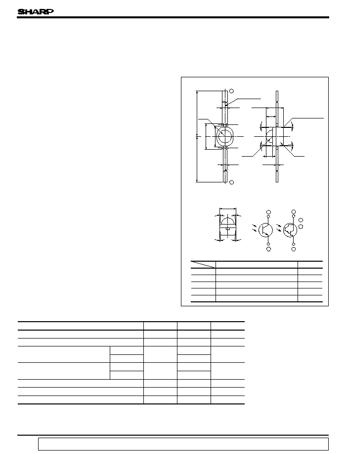
Outline Dimensions
s
Absolute Maximum Ratings
1. Compact double-end type package
s
Applications
1. Floppy disk drives
2. VCRs
3. Audio equipment
*3 For 3 seconds at the position of 2.5mm from the edge of resin package
5
∞
5
∞
5
∞
5
∞
0.7
0.4
0.4
0.5
3.0
4.0
R1.0
g
2 Marking
1.5
0.25
1.0
R1.0
5
∞
5
∞
5
∞
5
∞
g
2
PT460
-
PT460F
-
-
PT461
PT461F
Red
PT465F
Yellow
( Ta = 25∞C)
*1
PT460/460F/465F
*2
PT461/461F
PT460
PT460F
PT465F
PT461
PT461F
2
2
1
1
1 Emitter
2 Collector
2
1
g
1 Epoxy resin
R0.3
Duble-end Type
Phototransistor
( Unit : mm)
Parameter
Symbol
Rating
Unit
Collector-emitter voltage
V
CEO
35
V
Emitter-collector voltage
V
ECO
6
V
Collector current
*1
I
C
20
mA
50
*2
Collector power dissipation
*1
P
C
50
mW
100
*2
Operating temperature
T
opr
- 25 to + 85
∞C
Storage temperature
T
stg
- 40 to + 85
∞C
*3
Soldering temperature
T
sol
260
∞C
3. Visible light cut-off type
( PT460F / PT461F / 465F )
g
1 Epoxy resin
data books, etc. Contact SHARP in order to obtain the latest version of the device specification sheets before using any SHARP's device.
"
"
In the absence of confirmation by device specification sheets, SHARP takes no responsibility for any defects that occur in equipment using any of SHARP's devices, shown in catalogs,
2. Taping package ( 2 000pcs. /reel )
( PT
xxx
T )
Transparent resin
Visible light cut-off resin (black )
Light blue transparent resin
Visible light cut-off resin (black )
Visible light cut-off resin (black )
2.6
MAX.
15.5
MIN.
14.0
MIN.
2.5
±
0.2
s
Electro-optical Characteristics
( Ta= 25∞C)
PT460/PT460F/PT461/PT461F/PT465F
Parameter
Symbol
Conditions
MIN.
TYP.
MAX.
Unit
Collector current
PT460
I
C
V
CE
= 5V
*4
E
e
= 1mW/cm
2
0.18
-
1.20
mA
PT460F
0.11
-
0.90
PT465F
0.11
-
0.50
PT461
V
CE
= 5V
*4
E
e
= 0.01mW/cm
2
0.20
-
1.20
PT461F
0.14
-
0.98
Collector dark current
PT460/460F/465F
I
CEO
E
e
= 0, V
CE
= 20V
-
-
0.1
µ
A
PT461/461F
E
e
= 0, V
CE
= 10V
-
-
1.0
Collector-emitter
saturation voltage
PT460/PT460F
V
CE( sat )
E
e
= 10mW/cm
2
-
0.2
0.4
V
I
C
= 0.5mA
PT465F
PT461/PT461F
E
e
= 1mW/cm
2
-
-
1.2
I
C
= 2.5mA
Collector-emitter breakdown voltage
BV
CEO
I
C
= 0.1mA, E
e
= 0
35
-
-
V
Emitter-collector breakdown voltage
BV
ECO
I
C
= 0.01mA, E
e
= 0
6
-
-
V
Peak sensitivity
wavelength
PT460/PT461
p
-
-
800
-
nm
PT460F/461F/465F
-
860
-
PT460/460F/465F
t
r
V
CE
= 20V, I
C
= 1mA
R
L
= 1k
-
10
40
µ
s
t
f
-
8
35
PT461/461F
t
r
V
CE
= 2V, I
C
= 10mA
R
L
= 100
-
400
µ
s
-
300
t
f
Half sensitivity angle
-
-
± 50
-
*4 E
e
: Irradiance by CIE standard light source A (Tungsten Lamp)
- 25
0
25
50
75
100
125
0
20
40
60
80
100
120
50
85
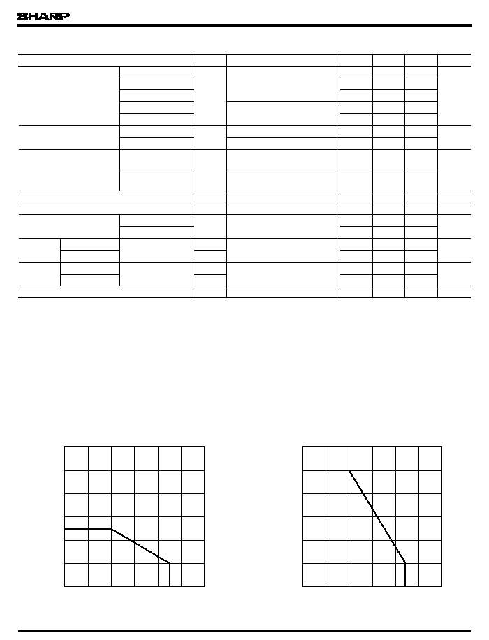
Ambient temperature T
a
(∞C)
Collector power dissipation P
C
(
mW
)
- 25
0
25
50
75
100
125
0
100
20
40
60
80
120
85
Collector power dissipation P
C
(
mW
)
Ambient temperature T
a
(∞C)
Ambient Temperature
Ambient Temperature
( PT461/461F )
Response
time
Rise time
Fall time
Response
time
Rise time
Fall time
( PT460/460F/465F )
Fig. 1-a Collector Power Dissipation vs.
Fig. 1-b Collector Power Dissipation vs.
2 000
1 500
∞
PT460/PT460F/PT461/PT461F/PT465F
Relative collector current
(
%
)
50
75
- 25
50
0
25
75
100
100
125
150
10
- 10
10
- 11
10
- 9
5
- 25
5
5
25
0
50
10
- 6
10
- 7
10
- 8
10
- 4
10
- 5
5
5
5
5
5
100
75
0
25
50
75
100
125
10
-6
10
-7
10
-8
10
-9
10
-10
Relative collector current
(
%
)
0
25
50
75
100
125
150
0
20
40
60
80
100
120
140
160
Collector current I
C
(
mA
)
0
2.5
5.0
7.5
10
12.5
15.0
0
2
4
6
8
10
12
Irradiance E
e
( mW/cm
2
)
Collector current I
C
(
mA
)
0.1
1
10
1.0
10
100
PT460
0.01
100
0.1
PT461
PT461F
Collector dark current I
CEO
(
A
)
PT460F/ 465F
Irradiance E
e
( mW/cm
2
)
Collector dark current I
CEO
(
A
)
Ambient temperature Ta ( ∞C )
Ambient temperature Ta (∞C )
Ambient temperature Ta ( ∞C )
Ambient temperature Ta ( ∞C )
V
CE
= 5V
T
a
= 25∞C
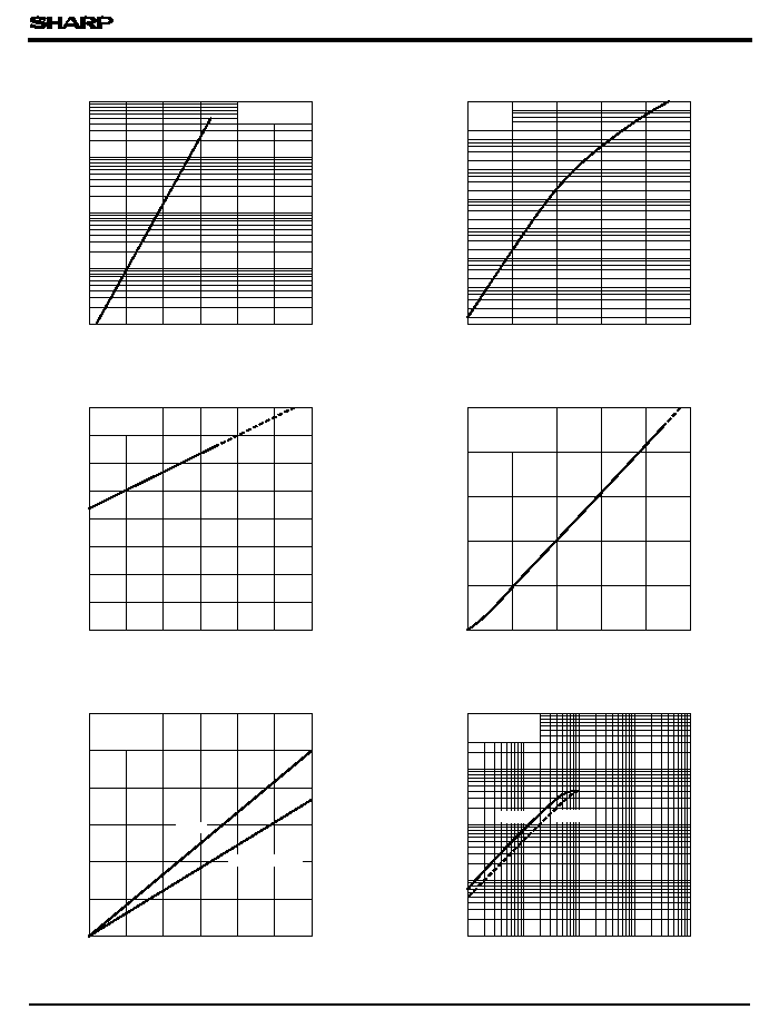
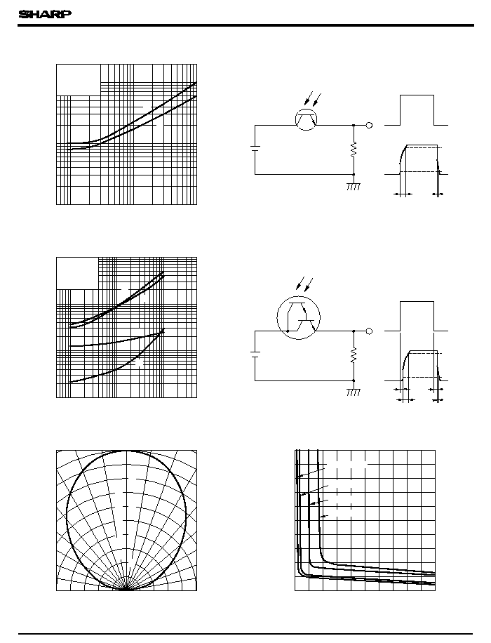
Fig. 4-a Collector Current vs. Irradiance
( PT460/460F/465F )
Fig. 4-b Collector Current vs. Irradiance
Fig. 2-a Collector Dark Current vs.
Ambient Temperature
( PT460/460F/465F )
Fig. 2-b Collector Dark Current vs.
( PT461/461F )
Fig. 3-a Relative Collector Current vs.
Ambient Temperature
( PT460/460F/465F )
Fig. 3-b Relative Collector Current vs.
Ambient Temperature
( PT461/461F )
175
V
CE
= 20V
V
CE
= 10V
V
CE
= 5V
E
e
= 1mW/cm
2
V
CE
= 10V
E
V
= 2lx
V
CE
= 5V
T
a
= 25∞C
Ambient Temperature
150
( PT461/461F )
PT460/PT460F/PT461/PT461F/PT465F
Collector-emitter voltage V
CE
(V)
Collector current I
C
(
mA
)
0
5
10
15
20
25
30
0
2
4
6
8
10
12
E
e
7.5mW/cm
2
5.0mW/cm
2
2.5mW/cm
2
1.0mW/cm
2
Collector-emitter voltage V
CE
(V)
Collector current I
C
(
mA
)
0
5
10
15
25
20
30
12
0
2
8
4
6
10
E
e
7.5mW/cm
2
5.0mW/cm
2
2.5mW/cm
2
1.0mW/cm
2
Collector-emitter voltage V
CE
(V)
Collector current I
C
(
mA
)
0
2
4
6
8
10
0
5
10
15
20
25
E
e
0.15mW/cm
2
0.1mW/cm
2
0.08mW/cm
2
0.06mW/cm
2
0.04mW/cm
2
Collector-emitter voltage V
CE
(V)
Collector current I
C
(
mA
)
0
2
4
6
10
8
0
E
e
2
4
6
8
10
12
0.1mW/cm
2
0.08mW/cm
2
0.06mW/cm
2
0.04mW/cm
2
0.15mW/cm
2
Wavelength
( nm )
Relative sensitivity
(
%
)
300
500
0
20
40
60
80
100
1000
300
Relative sensitivity
(
%
)
0
100
20
40
60
80
Wavelength
( nm )
500
1000
PT460
PT461
PT461F
14
16
T
a
= 25∞C
T
a
= 25∞C
T
a
= 25∞C
T
a
= 25∞C
Fig. 6-a Spectral Sensitivity
( PT460/460F/465F )
Fig. 6-b Spectral Sensitivity
( PT461/461F )
T
a
= 25∞C
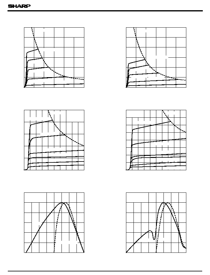
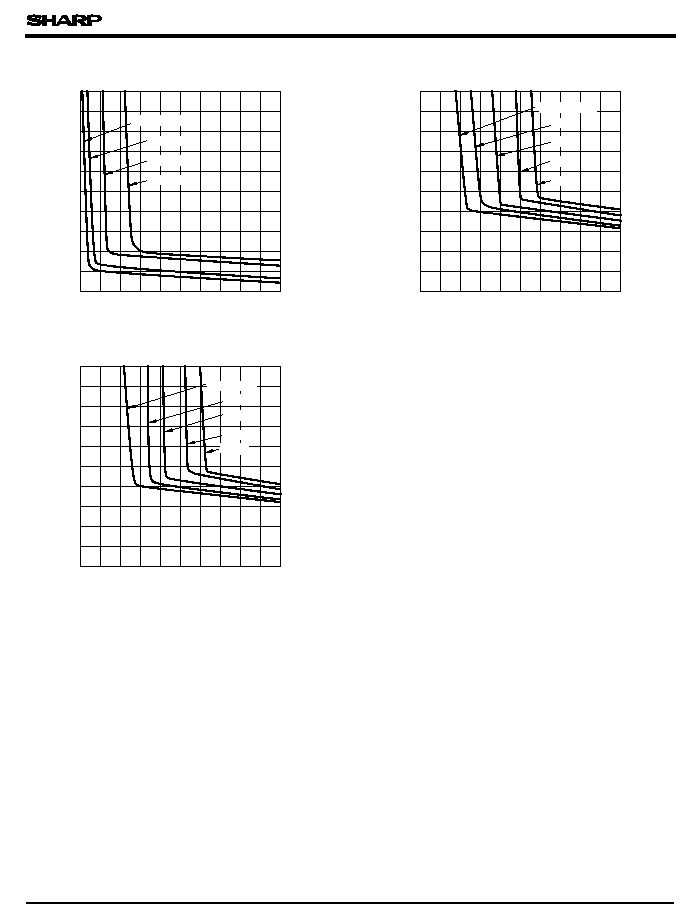
Fig. 5-a Collector Current vs.
Collector-emitter Voltage
(PT460 )
Fig. 5-b Collector Current vs.
Collector-emitter Voltage
( PT460F/465F )
Fig. 5-c Collector Current vs.
Collector-emitter Voltage
(PT461 )
Fig. 5-d Collector Current vs.
Collector-emitter Voltage
(PT461F )
= 10mW/cm
2
= 10mW/cm
2
= 0.2mW/cm
2
= 0.2mW/cm
2
P
C( MAX. )
P
C( MAX. )
T
a
= 25∞C
P
C( MAX. )
PT460F/465F
P
C( MAX.)
Response time
(
µ
s
)
5
L
(
)
1
2
500
50
10
20
100 200
5000
1000
V
CE
= 2V
I
C
= 10mA
T
a
= 25∞C
T
a
= 25∞C
I
C
= 1mA
V
CE
= 20V
L
( k
)
5
50
5
10
20
200
100
500
1000
2
1
10
20
100
50
t
f
t
d
t
s
t
r
2
1
5
10
50
20
100
t
r
t
f
t
r
t
d
Output
10
%
t
f
t
s
t
r
V
CC
R
L
Output Input
Output
V
CC
Output
R
L
Input
90
%
t
f
10
%
90
%
Relative sensitivity
(
%
)
20
Angular displacement
100
+ 10∞
40
60
80
- 10∞
- 20∞
0∞
+ 20∞
- 90∞
- 80∞
- 70∞
- 60∞
- 50∞
- 40∞
- 30∞
+ 90∞
+ 80∞
+ 70∞
+ 60∞
+ 50∞
+ 40∞
+ 30∞
0
2
4
6
8
10
0
0.2
0.4
0.6
0.8
1.0
I
C
= 0.05mA
I
C
= 0.1mA
I
C
= 0.5mA
I
C
= 1.0mA
0
Test Circuit for Response Time
( PT460/460F/465F )
Test Circuit for Response Time
( PT461/461F )
Fig. 8 Sensitivity Diagram
(PT460 )
PT460/PT460F/PT461/PT461F/PT465F
Fig. 7-a Response Time vs.
( PT460/PT460F/465F )
Fig. 7-b Response Time vs.
( PT461/461F )
Fig. 9-a Collector-emitter Saturation
Voltage vs. Irradiance
Collector-emitter saturation voltage
V
CE
( sat
)
(
V
)
Irradiance E
e
( mW/cm
2
)
Response time t
rf
(
µ
s
)
, t
Load Resistance
Load resistance R
Load Resistance
Load resistance R
0
2
4
6
8
10
0.2
0.4
0.6
0.8
1.0
0.1mA
0.5mA
1.0mA
0.01
0.1
1
0
1
1mA
2mA
5mA
10mA
0.01
0.1
1
0
1
2
1mA
2mA
5mA
10mA
PT460/PT460F/PT461/PT461F/PT465F
Fig. 9-b Collector-emitter Saturation
Voltage vs. Irradiance
( PT460F/465F )
Fig. 9-c Collector-emitter Saturation
Voltage vs. Irradiance
(PT461 )
Fig. 9-d Collector-emitter Saturation
Voltage vs. Irradiance
(PT461F )
I
C
= 0.05mA
I
C
= 0.5mA
Collector-emitter saturation voltage
V
CE
( sat
)
(
V
)
Collector-emitter saturation voltage
V
CE
( sat
)
(
V
)
I
C
= 0.5mA
Collector-emitter saturation voltage
V
CE
( sat
)
(
V
)
( mW/cm
2
)
Irradiance E
e
( mW/cm
2
)
Irradiance E
e
( mW/cm
2
)
Irradiance E
e
S
h
S
S
S
S
S
T
W
T
Blue tape
White tape
Z
P
Z
t
t
L1
L2
H
A
:
Center of
cathode marking
51
52
Label
260
( Note 2 ) The lead's overlapping length on the tape.
( Note
2 ) t
W
L2-
L1
T
Z
h
S
H
A
26
+ 1.5
- 0.0
5
+ 0.5
- 0.5
-
6
+ 10
- 10
1.2
MAX
0.5
MAX
0.8
MAX
0.5
MIN
2.5
MAX
(4.5)
( Note
1) p
*
A
Blue tape (Collector )
White tape (Emitter )
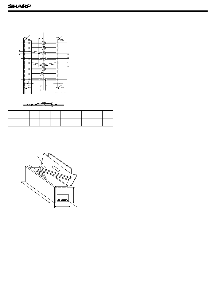
( 1) Packing form
Box type
are not stuffed.
c ) For the taping of collector pin, blue tape is used, and for emitter pin, white tape in used.
( 2) Packing quantity
PT460/PT460F/PT461/PT461F/PT465F
s
Packing Specification (PT
xxx
T)
( Note 1 ) Tolerance of 20 pitches is ± 2mm.
a ) The tape is zigzag-folded with 50 pcs. of phototransistor per fold.
b ) Phototransistor inserting portions for 50 to 60 pcs. on the tape's starting and ending parts
2 000 pcs. per box
q
Please refer to the chapter "Precautions for Use."
s
Taping Specifications (PT
xxx
T)
*