S1WB(A)60B
600V 1A
Copyright & Copy;2000 Shindengen Electric Mfg.Co.Ltd
Case : 1W
SHINDENGEN
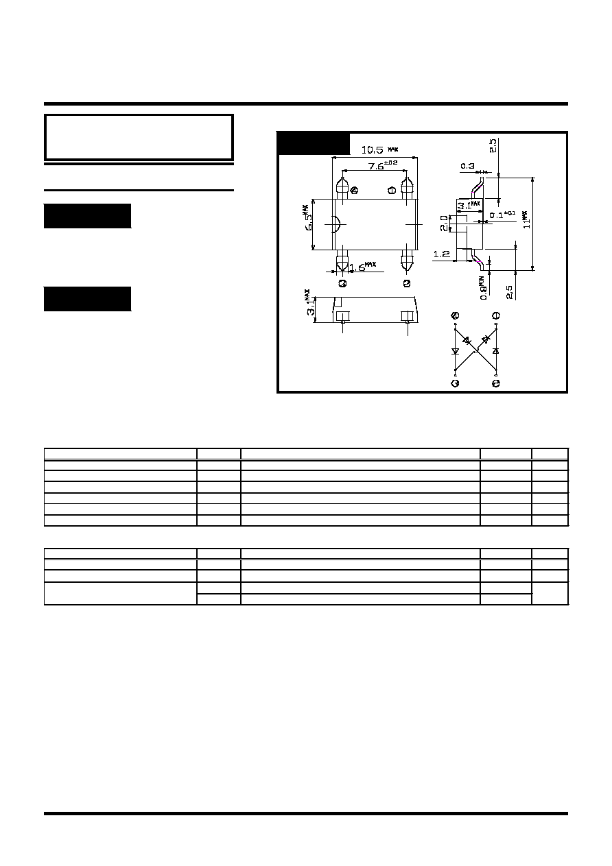
OUTLINE DIMENSIONS
Unit : mm
RATINGS
Case : 1W
Switching power supply
Home Appliances, Office Equipment
Telecommunication, Factory Automation
APPLICATION
Small SMT
High IFSM
Applicable to Automatic Insertion
FEATURES
General Purpose Rectifiers
SMT Bridges
Absolute Maximum Ratings (If not specified Tl=25)
Item
Symbol
Conditions
Ratings
Unit
Storage Temperature
Tstg
-40150
Operating Junction Temperature
Tj
150
Maximum Reverse Voltage
V
RM
600
V
Average Rectified Forward Current
I
O
50Hz sine wave, R-load, Ta=25
1
A
Peak Surge Forward Current
I
FSM
50Hz sine wave, Non-repetitive 1 cycle peak value, Tj=25
50
A
Current Squared Time
I
2
t
1mst10msTj=25
16
A
2
s
Electrical Characteristics (If not specified Tl=25)
Item
Symbol
Conditions
Ratings
Unit
Forward Voltage
V
F
I
F
=0.5A, Pulse measurement, Rating of per diode
Max.1.0
V
Reverse Current
I
R
V
R
=V
RM
,
Pulse measurement, Rating of per diode
Max.10
A
Thermal Resistance
jl
junction to lead
Max.10
/W
ja
junction to ambient
Max.65

0
0.5
1
1.5
2
2.5
3
3.5
4
0
0.2
0.4
0.6
0.8
1
1.2
1.4
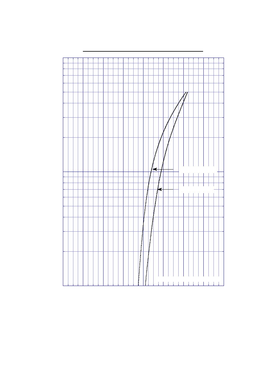
S1WB(A)60B
Forward Power Dissipation
SIN
Average Rectified Forward Current I
O
[A]
Forward Power Dissipation P
F
[W]
Tj = 150
∞
C
Sine wave
0
20
40
60
80
100
120
140
160
0
0.2
0.4
0.6
0.8
1
1.2
1.4
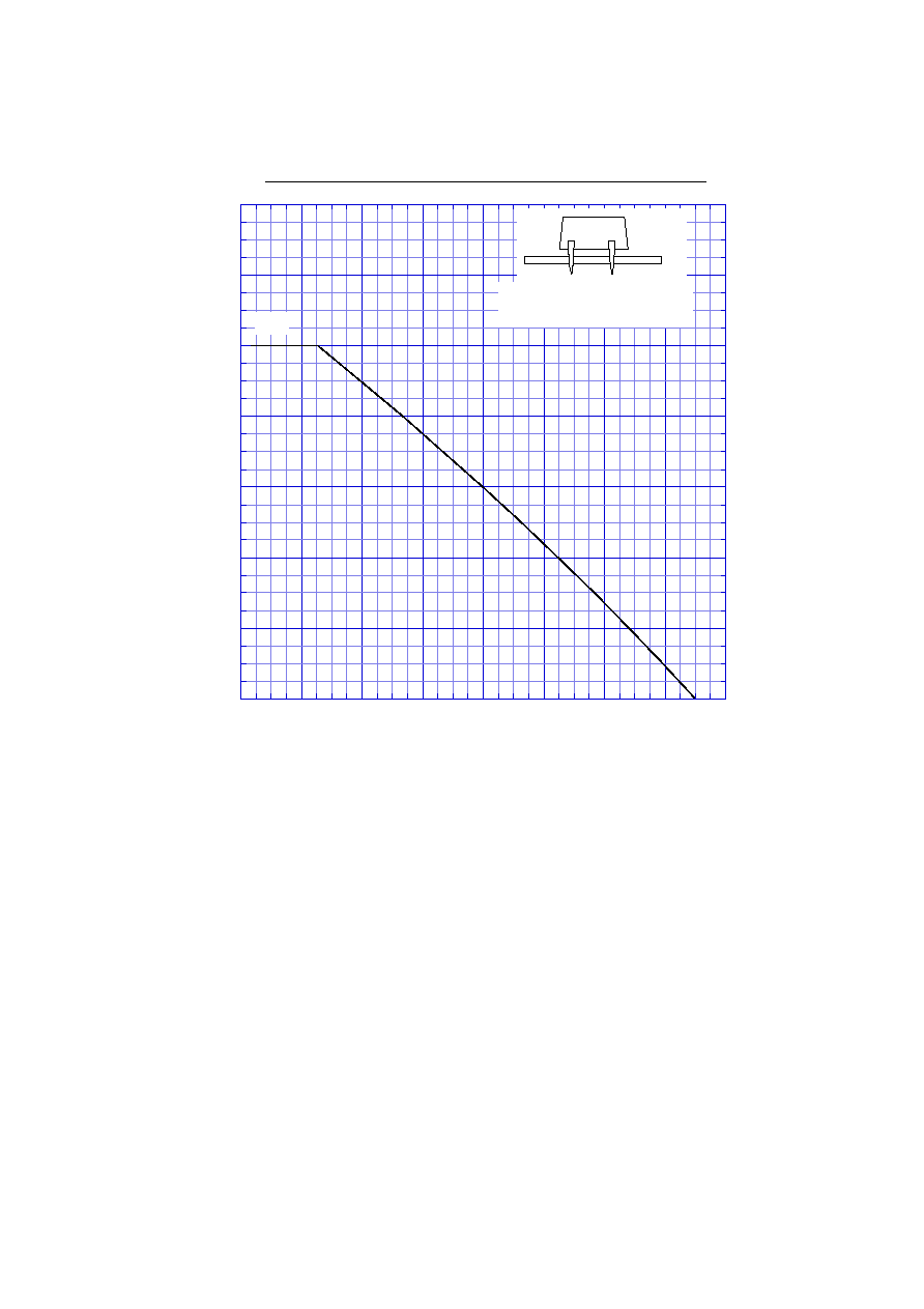
S1WB(A)60B
Derating Curve
SIN
PCB
Ambient Temperature Ta [
∞
C]
Average Rectified Forward Current I
O
[A]
Glass-epoxy substrate
Soldering land 3mm
V
R
= V
RM
Sine wave
R-load
Free in air
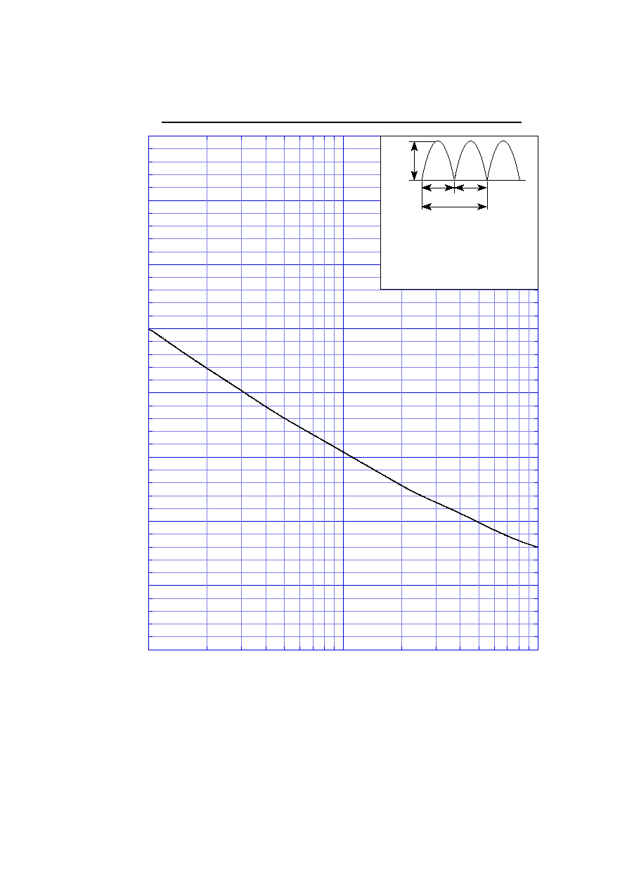
Peak Surge Forward Capability
0
10
20
30
40
50
60
70
80
1
10
100
S1WB(A)60B
2
5
20
50
I
FSM
10ms 10ms
1 cycle
Number of Cycles [cycles]
Peak Surge Forward Current I
FSM
[A]
non-repetitive,
sine wave,
Tj=25
∞
C before
surge current is applied