Semiconductor Group
1
Jan-08-1997
BBY 51-07
Silicon Tuning Diode
∑ High Q hyperabrupt dual tuning diode
∑ Designed for low tuning voltage operation
∑ For VCO's in mobile communications equipment
Type
Marking Ordering Code
Pin Configuration
Package
BBY 51-07
HHs
Q62702-
1 = C1 2 = C2 3 = A2 4 = A1 SOT-143
Maximum Ratings per diode
Parameter
Symbol
Values
Unit
Diode reverse voltage
V
R
7
V
Forward current
I
F
20
mA
Operating temperature range
T
op
- 55 ... + 150
∞C
Storage temperature
T
stg
- 55 ... + 150

Semiconductor Group
2
Jan-08-1997
BBY 51-07
Electrical Characteristics at
T
A
=25∞C, unless otherwise specified
Parameter
Symbol
Values
Unit
min.
typ.
max.
DC characteristics per diode
Reverse current
V
R
= 6 V,
T
A
= 25 ∞C
V
R
= 6 V,
T
A
= 65 ∞C
I
R
-
-
-
-
200
10
nA
AC characteristics per diode
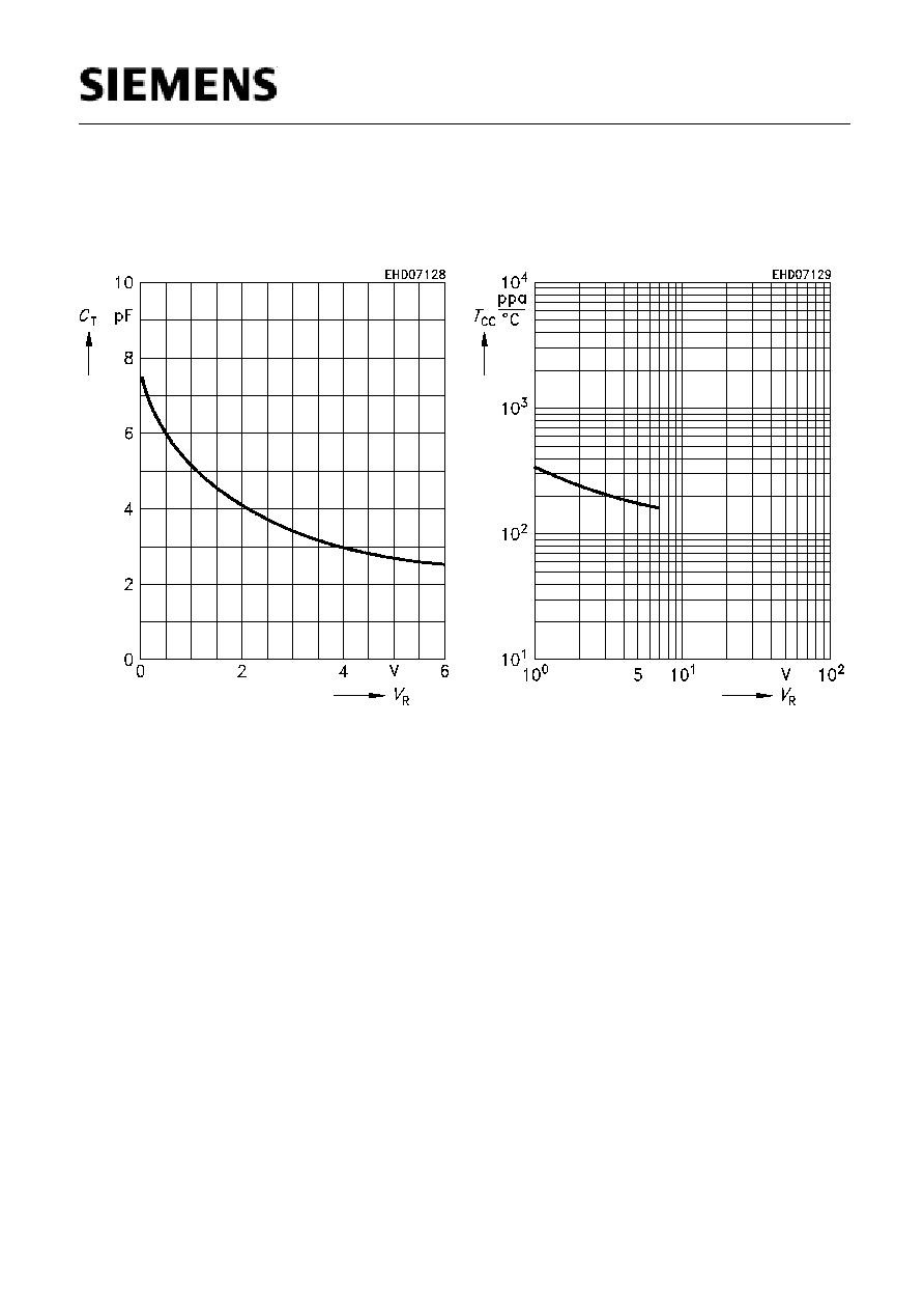
Diode capacitance
V
R
= 1 V,
f = 1 MHz
V
R
= 2 V,
f = 1 MHz
V
R
= 3 V,
f = 1 MHz
V
R
= 4 V,
f = 1 MHz
C
T
2.6
2.9
3.6
4.8
3.1
3.5
4.2
5.3
3.5
4.2
5
6
pF
Capacitance ratio
V
R
= 1 V,
V
R
= 4 V,
f = 1 MHz
C
T1
/
C
T4
1.55
1.75
2.15
-
Capacitance difference
V
R
= 1 V,
V
R
= 3 V,
f = 1 MHz
C
1V
-
C
3V
1.4
1.78
2.2
pF
Capacitance difference
V
R
= 3 V,
V
R
= 4 V,
f = 1 MHz
C
3V
-
C
4V
0.3
0.5
0.7
Series resistance
V
R
= 1 V,
f = 1 GHz
r
s
-
0.37
-
Case capacitance
f = 1 MHz
C
C
-
0.12
-
pF
Series inductance chip to ground
L
s
-
2
-
nH