 | –≠–ª–µ–∫—Ç—Ä–æ–Ω–Ω—ã–π –∫–æ–º–ø–æ–Ω–µ–Ω—Ç: FP201L100 | –°–∫–∞—á–∞—Ç—å:  PDF PDF  ZIP ZIP |

Semiconductor Group
1
07.96
The differential magnetoresistive sensor FP 201 L 100 consists of two magnetically
biased magneto resistors made from L-type InSb/NiSb, which in their unbiased state
each have a basic resistance of about 125
. They are series coupled as a voltage
divider and are encapsuled in plastic as protection against mechanical stresses. This
magnetically actuated sensor can be implemented as a direction dependent contactless
switch where it shows a voltage change of about 1.3 V/mm in its linear region.
Type
Ordering Code
FP 201 L 100
Q65210-L101
Differential Magnetoresistive Sensor
FP 201 L 100
Dimensions in mm
Features
∑ Extremely high output
voltage
∑ 2 independently biased
magnetic circuits
∑ Robust housing
∑ Signal amplitude
independent of operating
speed
∑ Screw mounting possible
Typical applications
∑ Detection of speed
∑ Detection of position
∑ Detection of sense of rotation

Semiconductor Group
2
FP 201 L 100
Maximum ratings
Characteristics (
T
A
= 25
∞
C)
This sensor is operated by a permanent magnet. Using the arrangement as shown in
Fig. 1, the permanent magnet increases the internal biasing field through the righthand
side magneto resistor (connections 2-3), and reduces the field through the left side
magneto resistor (connections 1-2). As a result the resistance value of MR
2-3
increases
while that of MR
1-2
decreases. When the permanent magnet is moved from left to right
the above-mentioned process operates in reverse.
Parameter
Symbol
Value
Unit
Operating temperature
T
A
≠ 25 / + 100
∞
C
Storage temperature
T
stg
≠ 25 / + 110
∞
C
Power dissipation
1)
P
tot
600
mW
Supply voltage
2)
V
IN
10
V
Insulation voltage between
terminals and casing
V
I
> 100
V
Thermal conductivity
G
thcase
G
thA
10
5
mW/K
mW/K
Nominal supply voltage
V
IN N
5
V
Total resistance, (
=
,
I
1 mA)
R
1-3
700
...
1400
Center symmetry
3)
(
=
)
M
10
%
Offset voltage
4)
(at
V
IN N
and
=
)
V
0
130
mV
Open circuit output voltage
5)
(
V
IN N
and
= 0.5 mm)
V
out pp
> 2.2
V
Cut-off frequency
f
c
> 7
kHz
1) Corresponding to diagram
P
tot
=
f
(
T
case
)
2) Corresponding to diagram
V
IN
=
f(T)
3)
4)
Corresponding to measuring circuit in Fig. 3
5) Corresponding to measuring circuit in Fig. 3 and arrangement as shown in Fig. 2
M
R
1
2
≠
R
2
3
≠
≠
---------------------------------
=
◊
100% for
R
1-2
>
R
2-3
R
1
2
≠

Semiconductor Group
3
FP 201 L 100
Fig. 1
Sensor operating by external permanent magnet
Fig. 2
Fig. 3
Measuring arrangement with a permanent
Measuring circuit and output
magnet Alnico 450
waveform
= 4 mm, 6 mm long
A steeper gradient is achieved when using a horseshoe magnet.
Semiconductor Group
4
FP 201 L 100
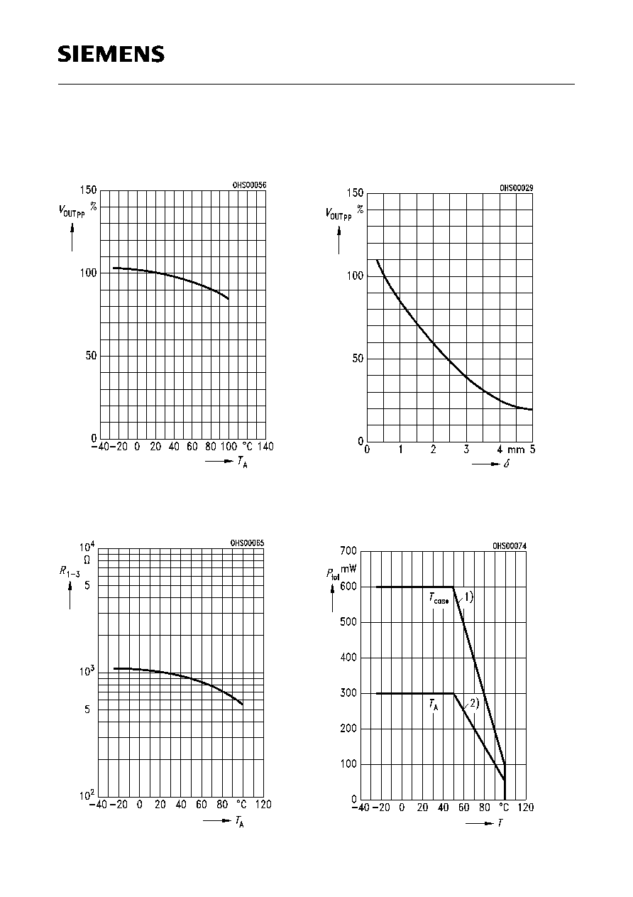
Output voltage (typical) versus
temperature
V
OUTpp
=
f
(
T
A
),
= 0.5 mm
V
OUTpp
at
T
A
= 25
∞
C
100%
Total resistance (typical)
versus temperature
R
1-3
=
f
(
T
A
),
=
^
=
Output voltage (typical) versus
airgap
V
OUTpp
=
f
(
),
T
A
= 25
∞
C
V
OUTpp
at
= 0.5 mm
100%
Max. power dissipation
versus temperature
P
tot
=
f
(
T
),
=
,
T
=
T
case
,
T
A
^
=

Semiconductor Group
5
FP 201 L 100
Maximum supply voltage
versus temperature
V
IN
=
f
(
T
),
=
,
T
=
T
case
,
T
A
1) Sensor mounted with good thermal contact to a heat sink
2) Operation in still air