Semiconductor Group
1
07.96
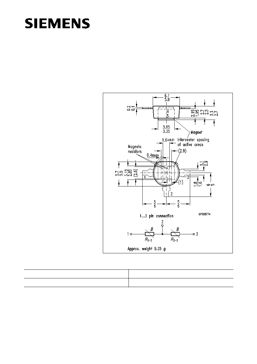
The differential magnetoresistive sensor FP 212 L 100-22 consists of two series coupled
magneto resistors (L-type InSb/NiSb semiconductor resistors whose value can be
magnetically controlled) which are mounted onto an insulated ferrite substrate. The
sensor is encapsulated in a plastic package and has three connecting terminals.
The basic resistance of the total system is 2
◊
100
. A permanent magnet which supplies
a biasing magnetic field is fixed on the base of the sensor.
Type
Ordering Code
FP 212 L 100-22
Q65212-L1004
Differential Magnetoresistive Sensor
FP 212 L 100-22
Dimensions in mm
Features
∑ High output voltage
∑ High operating temperature
∑ Robust plastic housing
∑ Biasing magnet build in
∑ Signal amplitude is speed
independent
∑ Marking silver
Typical applications
∑ Detection of speed
∑ Detection of position
∑ Detection of sense of rotation
∑ Angle encoder
∑ Linear position sensing

Semiconductor Group
2
FP 212 L 100-22
Maximum ratings
Characteristics (
T
A
= 25
∞
C)
Measuring arrangements
By approaching a soft iron part close to the sensor a change in its resistance is obtained.
The potential divider circuit of the magneto resistor causes a reduction in the
temperature dependence of the output voltage
V
OUT
.
Parameter
Symbol
Value
Unit
Operating temperature
T
A
≠ 40 / + 140
∞
C
Storage temperature
T
stg
≠ 40 / + 150
∞
C
Power dissipation
1)
P
tot
450
mW
Supply voltage
2)
V
IN
10
V
Insulation voltage between
terminals and magnet
V
I
> 60
V
Thermal conductivity
(when soldered)
G
thA
5
mW/K
Nominal supply voltage
V
IN N
5
V
Total resistance, (
=
,
I
1 mA)
R
1-3
220
...
400
Center symmetry
3)
(
=
)
M
10
%
Offset voltage
4)
(at
V
IN N
and
=
)
V
0
130
mV
Open circuit output voltage
5)
(
V
IN N
and
= 0.2 mm)
V
out pp
> 1000
mV
Cut-off frequency
f
c
> 20
kHz
1) Corresponding to diagram
P
tot
=
f
(
T
A
)
2) Corresponding to diagram
V
IN
=
f(T
A
)
3)
4) Corresponding to measuring circuit in Fig. 2
5) Corresponding to measuring circuit in Fig. 2 and arrangement as shown in Fig. 1
M
R
1
2
≠
R
2
3
≠
≠
----------------------------
=
◊
100% for
R
1-2
>
R
2-3
R
1
2
≠

Semiconductor Group
3
FP 212 L 100-22
1. Digital revolution counting
For digital revolution counting, the sensor should be actuated by a magnetically soft iron
toothed wheel. The tooth spacing should correspond to about twice the magneto resistor
intercenter spacing i.e 2
◊
1.6 mm (see Fig. 1).
The two resistors of the sensor are supplemented by two additional resistors in order to
obtain the sensor output voltage as a bridge voltage
V
OUT
. The output voltage
V
OUT
without excitation then is 0 V when the offset is compensated.
Fig. 1
Schematic representation of a toothed wheel actuating an FP 212 L 100-22
Fig. 2
Measuring circuit and output voltage
V
OUT
waveform
Semiconductor Group
4
FP 212 L 100-22
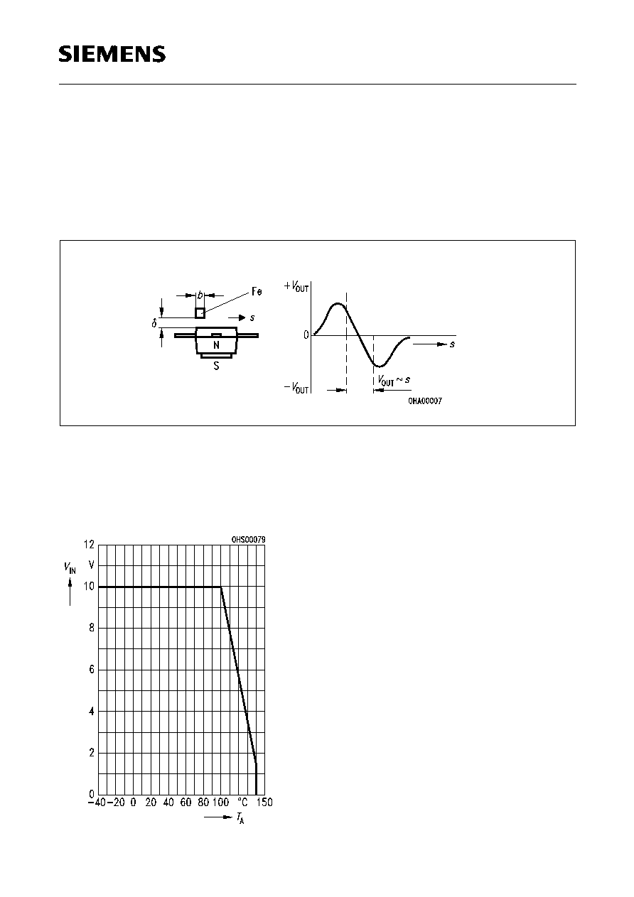
2. Linear distance measurement
To convert small distances into a proportional electric signal, a small soft iron part of
definite width (e.g.
b
= 1.8 mm) is moved over the face of the sensor.
Proportional signals for distances up to 1.5 mm can be obtained in this way. The
sinusoidal output signal gives a voltage proportional to distance in the zero crossover
region (see Fig. 3).
Fig. 3
Measuring arrangement for analogue application
Maximum supply voltage
versus temperature
V
IN
=
f
(
T
A
)
Semiconductor Group
5
FP 212 L 100-22
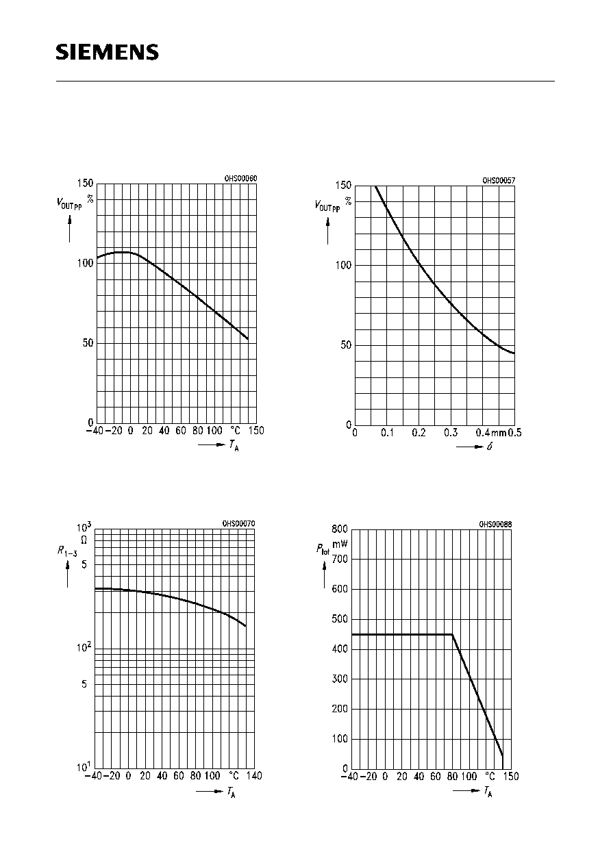
Output voltage (typical) versus
temperature
V
OUTpp
=
f
(
T
A
),
= 0.2 mm
V
OUTpp
at
T
A
= 25
∞
C
100%
Total resistance (typical)
versus temperature
R
1-3
=
f
(
T
A
),
=
^
=
Output voltage (typical) versus
airgap
V
OUTpp
=
f
(
),
T
A
= 25
∞
C
V
OUTpp
at
= 0.2 mm
100%
Max. power dissipation
versus temperature
P
tot
=
f
(
T
A
),
=
^
=