 | –≠–ª–µ–∫—Ç—Ä–æ–Ω–Ω—ã–π –∫–æ–º–ø–æ–Ω–µ–Ω—Ç: FP425L90 | –°–∫–∞—á–∞—Ç—å:  PDF PDF  ZIP ZIP |
Semiconductor Group
1
07.96
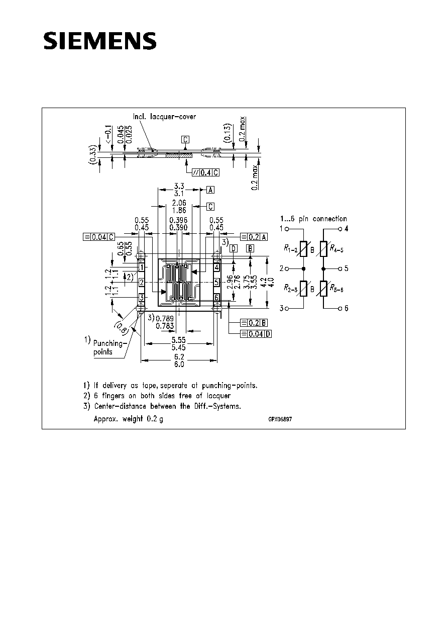
Differential Magneto Resistor
FP 425 L 90
Dimensions in mm
Features
∑ Double differential magneto resistor on one carrier
∑ Accurate intercenter spacing
∑ High operating temperature range
∑ High output voltage
∑ Compact construction
∑ Available in strip form for automatic assembly
∑ Optimized intercenter spacing on modules
m
= 0.5 mm
∑ Reduced temperature dependence of offset
voltage
Typical applications
∑ Incremental angular encoders
∑ Detection of sense of rotation
∑ Detection of speed
∑ Detection of position

Semiconductor Group
2
FP 425 L 90
The double differential magneto resistor assembly consists of two pairs of magneto
resistors, (L-type InSb/NiSb semiconductor resistors whose resistance value can be
magnetically controlled), which are fixed to a silicon substrate. Contact to the magneto
resistors is achieved using a copper/polyimide carrier film known as TAB.
The basic resistance of each of the magneto resistors is 90
. The two series coupled
pairs of magneto resistor are actuated by an external magnetic field or can be biased by
a permanent magnet and actuated by a soft iron target.
Type
Ordering Code
FP 425 L 90
Q65425-L90 (singular)
FP 425 L 90
Q65425-L0090E001 (taped)

Semiconductor Group
3
FP 425 L 90
Maximum ratings
Characteristics (
T
A
= 25
∞
C)
Parameter
Symbol
Value
Unit
Operating temperature
T
A
≠ 40 / + 175
∞
C
Storage temperature
T
stg
≠ 40 / + 185
∞
C
Power dissipation
1)
P
tot
800
mW
Supply voltage (
B
= 0.2 T,
T
A
= 25
∞
C)
V
IN
8
V
Thermal conductivity
≠attached to heatsink
≠in still air
G
thcase
G
thA
20
2
mW/K
mW/K
Nominal supply voltage (
B
= 0.2 T)
2)
V
INN
5
V
Basic resistance
(
I
< 1 mA,
B
= 0 T)
R
01-3
160 ≠ 280
Center symmetry
3)
M
3
%
Relative resistance change
(
R
0
=
R
01-3
,
R
04-6
at
B
= 0 T)
B
=
±
0.3 T
4)
B
=
±
1 T
R
B
/
R
0
> 1.7
> 7
≠
Temperature coefficient
B
= 0 T
B
=
±
0.3 T
B
=
±
1 T
TC
R
≠ 0.16
≠ 0.38
≠ 0.54
%/K
%/K
%/K
1)
T
=
T
case
2)
T
=
T
case
, T
< 80
∞
C
3)
4) 1 T = 1 Tesla = 10
4
Gauss
M
R
01
2
≠
R
02
3
≠
≠
--------------------------------
=
◊
100% for
R
01-2
>
R
02-3
R
01
2
≠
M
R
04
5
≠
R
05
6
≠
≠
--------------------------------
=
◊
100% for
R
04-5
>
R
05-6
R
04
5
≠
Semiconductor Group
4
FP 425 L 90
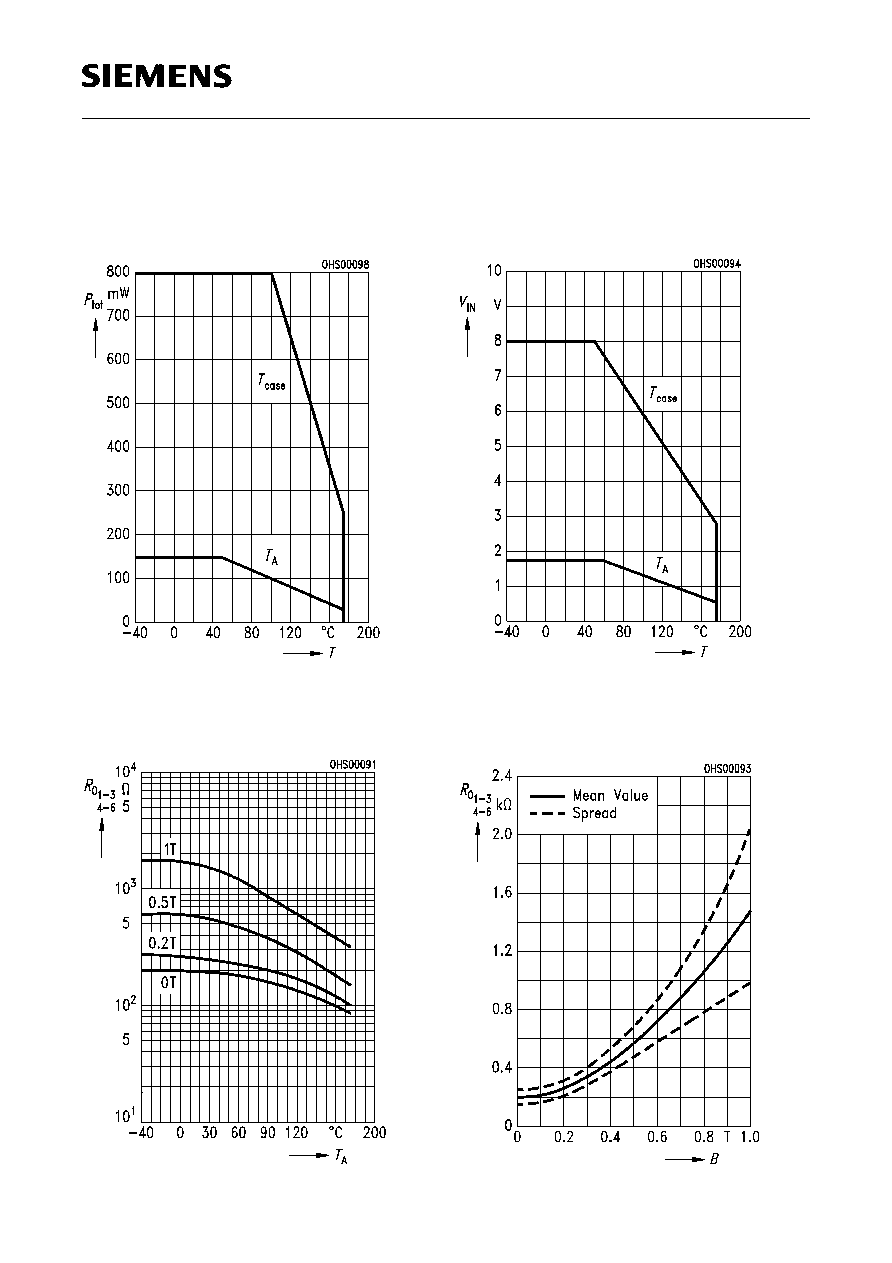
Max. power dissipation versus
temperature
P
tot
=
f
(
T
),
T
=
T
case
,
T
A
Typical MR resistance
versus temperature
R
01-3, 4-6
=
f
(
T
A
),
B
= Parameter
Maximum supply voltage
versus temperature
V
IN
=
f
(
T
),
B
= 0.2 T
Typical MR resistance
versus magnetic induction
B
R
01-3, 4-6
=
f
(
B
),
T
A
= 25
∞
C