BAR 63...
Semiconductor Group
1
Edition A01, 23.02.95
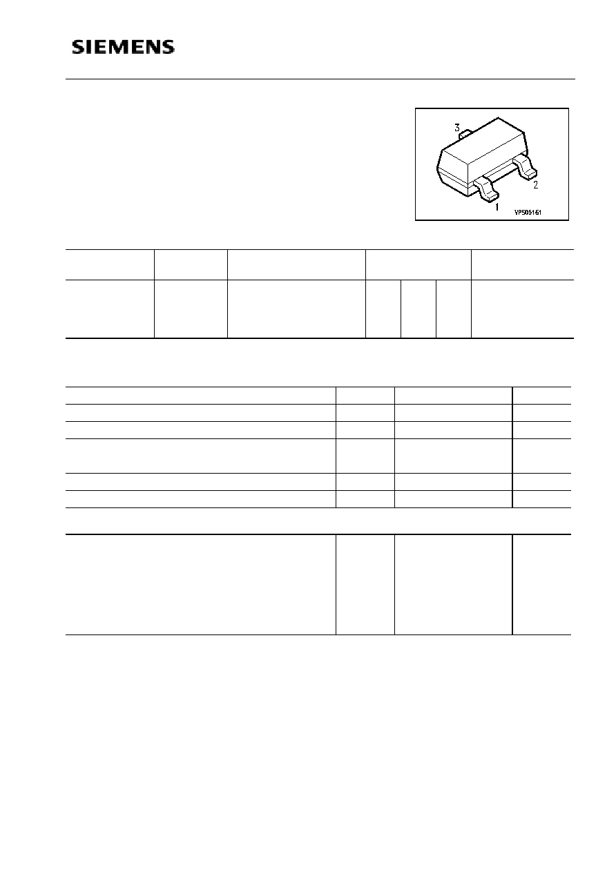
Type
Marking
Ordering code
(tape and reel)
Pin configuration
1 2 3
Package
1)
BAR 63
G3
Q62702-A1036
A
-
C
SOT-23
BAR 63-04
G4
Q62702-A1037
A
C
C/A
BAR 63-05
G5
Q62702-A1038
A
A
C/C
BAR 63-06
G6
Q62702-A1039
C
C
A/A
Maximum ratings
Parameter
Symbol
BAR 63
Unit
Reverse voltage
V
R
50
V
Forward current
I
F
100
mA
Total Power dissipation T
S
80∞C
BAR 63-04,-05,-06 T
S
55∞C
P
tot
250
250
mW
Operating temperature range
T
op
-55 +150∞C
∞
C
Storage temperature range
T
stg
-55...+150∞C
∞
C
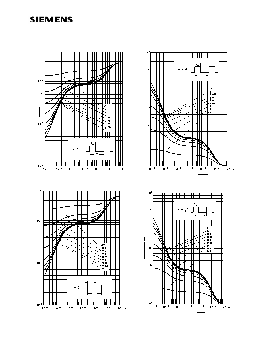
Thermal resistance
Junction-ambient
1)
BAR63
BAR 63-04,-05,-06
R
th JA
450
540
K/W
Junction-soldering point
BAR64
BAR63-04,-05,-06
R
th JS
280
380
_________________________
1)Package mounted on alumina 15mm x 16.7mm x 0.7mm
Silicon PIN Diode
l
PIN diode for high speed switching of RF signals
l
Low forward resistance
l
Very low capacitance
l
For frequencies up to 3 GHz
BAR 63...
Semiconductor Group
2
Edition A01, 23.02.95
Electrical characteristics
at
T
A
= 25
∞
C, unless otherwise specified.
Parameter
Symbol
Value
Unit
min.
typ.
max.
DC characteristics
Breakdown voltage
I
R
= 5
µ
A
V
(BR)
50
-
-
V
Reverse leakage
V
R
= 20 V
I
R
-
-
50
nA
Forward voltage
I
F
= 100 mA
V
F
-
0.95
1.2
V
Diode capacitance
V
R
= 0 V,
f = 100 MHz
C
T
-
0.3
-
pF
Diode capacitance
V
R
= 5 V,
f = 1 MHz
C
T
-
0.21
0.3
pF
Forward resistance
I
F
= 5 mA,
f = 100 MHz
I
F
= 10 mA,
f = 100 MHz
r
f
-
-
1.2
1
2
-
Charge carrier lifetime
I
F
= 10 mA,
I
R
= 6 mA,
I
R
= 3 mA
s
-
75
-
ns
Series inductance
L
s
-
1.4
-
nH
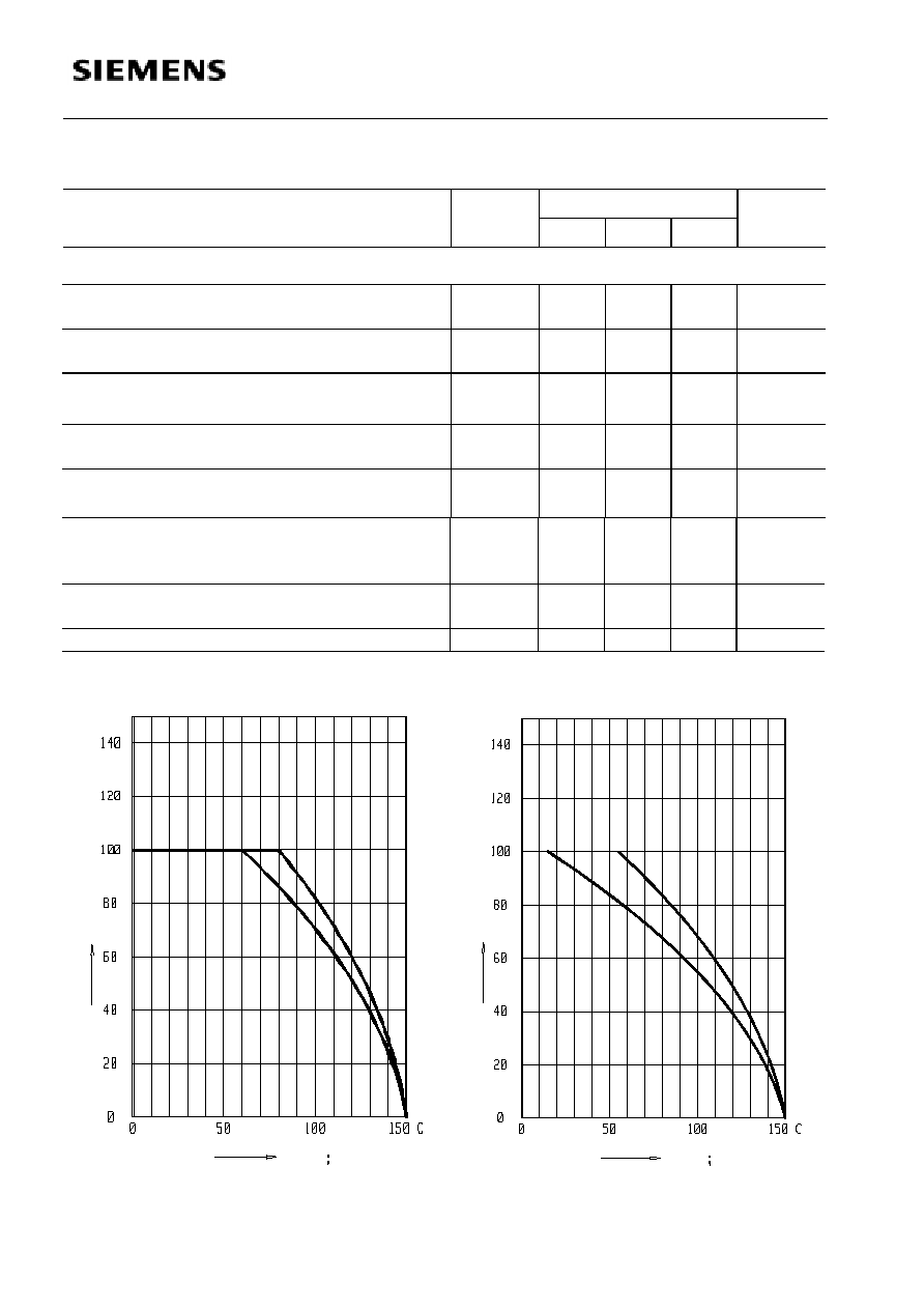
Forward current
I
F
=
f
(
T
A
*T
S
)
BAR63
Forward current
I
F
=
f
(
T
A
*T
S
)
per each Diode BAR63-04,-05,-06
T
T
A
S
I
F
mA
T
T
A
S
T
T
A
S
I
F
T
T
A
S
mA