 | –≠–ª–µ–∫—Ç—Ä–æ–Ω–Ω—ã–π –∫–æ–º–ø–æ–Ω–µ–Ω—Ç: Q62702-M9 | –°–∫–∞—á–∞—Ç—å:  PDF PDF  ZIP ZIP |

GaAs MMIC
CMY 91
________________________________________________________________________________________________________
Siemens Aktiengesellschaft
pg. 1/9
16.12.96
HL EH PD21
D a t a s h e e t
* GaAs mixer with integrated IF-amplifier for mobile
communication
* Frequency range 0.8 GHz to 2.5 GHz
* Very low power consumption (1mA typ.)
* Single positive supply voltage
* Operating voltage range: 2.7 to 6 V
* Miniature package MW6 based on SOT23
ESD: Electrostatic discharge sensitive device,
observe handling precautions!
6
5
4
3
2
1
LO
GND
RF
CAP
GND
IF
Type
Marking
Ordering code (taped)
Package 1)
CMY 91
M2
Q62702-M9
MW-6
RF(in)[6]
CAP(1)[1]
IF(out)[3]
LO(in)[4]
GND[2;5]
Maximum ratings
Symbol
Unit
Drain-source voltage
V
IF-GND
8
V
Gate-source voltage range
V
LO-GND
-5 ... 0
V
Drain current
I
IF
20
mA
RF- / LO-peak current
+I
RF,
+I
LO
2
mA
Channel temperature
TCh
150
∞C
Storage temperature range
Tstg
-55...+150
∞C
Total power dissipation
(T
S
= tbd ∞C)2)
Ptot
160
mW
Thermal resistance
Channel-soldering point GND
RthChS
350
K/W
1)
Dimensions see chapter Package Outlines
2) TS: Temperature measured at soldering point GND

GaAs MMIC
CMY 91
________________________________________________________________________________________________________
Siemens Aktiengesellschaft
pg. 2/9
16.12.96
HL EH PD21
Electrical characteristics at TA = 25∞C / VD = 3 V unless otherwise specified
Characteristics of 900MHz test and application circuit (see page app. circuit)
Parameters
Symbol
min
typ
max
Unit
Drain-source breakdown voltage
IIF = 500 µA
VLO-GND = 0 V
VRF-GND = 4 V
CAP-pin not connected
V
(BR)
IF-GND
8
-
-
V
Drain current
VRF-GND = 0 V
VLO-GND = 0 V
VIF-GND = 3 V
CAP-pin not connected
I
D
0.8
1
1.4
mA
Conversion gain
fRF = 920 MHz
fLO = 965 MHz
fIF = 45 MHz
PLO = -3 dBm
G
C
-
5.5
-
dB
Single sideband noise figure
fRF = 920 MHz
fLO = 965 MHz
fIF = 45 MHz
PLO = -3 dBm
F
SSB
-
9
-
dB
3rd order intermodulation
fRF = 920 MHz
fLO = 965 MHz
fIF = 45 MHz
PLO = -3 dBm
IP3
-
-2
-
dBm
LO/RF isolation
f = 965 MHz
Iso
LO/RF
-
11
-
dB
TA = 25∞C / VD = 3 V; CAP-pin connected to ground by 680
resistor
Parameters
Symbol
min
typ
max
Unit
Drain current
VRF-GND = 0 V
VLO-GND = 0 V
VIF-GND = 3 V
I
D
-
2.5
-
mA
Conversion gain
fRF = 920 MHz
fLO = 965 MHz
fIF = 45 MHz
PLO = -3 dBm
G
C
-
9.5
-
dB
Single sideband noise figure
fRF = 920 MHz
fLO = 965 MHz
fIF = 45 MHz
PLO = -3 dBm
F
SSB
-
8.0
dB
3rd order intermodulation
fRF = 920 MHz
fLO = 965 MHz
fIF = 45 MHz
PLO = -3 dBm
IP3
-
0
-
dBm
LO/RF isolation
f = 965 MHz
Iso
LO/RF
-
11
-
dB
Not used ports were terminated by 50
.
Please make sure that LO-signal is clean of noise and spurious at f = f
LO
+/- f
IF
GaAs MMIC
CMY 91
________________________________________________________________________________________________________
Siemens Aktiengesellschaft
pg. 3/9
16.12.96
HL EH PD21
Electrical characteristics at TA = 25∞C / VD = 3 V unless otherwise specified
Characteristics of 1450MHz application circuit (see page app. circuit)
Parameters
Symbol
min
typ
max
Unit
Drain-source breakdown voltage
IIF = 500 µA
VLO-GND = 0 V
VRF-GND = 4 V
CAP-pin not connected
V
(BR)
IF-GND
8
-
-
V
Drain current
VRF-GND = 0 V
VLO-GND = 0 V
VIF-GND = 3 V
CAP-pin not connected
I
D
0.8
1
1.4
mA
Conversion gain
fRF = 1450 MHz fLO = 1350 MHz
fIF = 100 MHz
PLO = -3 dBm
G
C
-
5.5
-
dB
Single sideband noise figure
fRF = 1450 MHz fLO = 1350 MHz
fIF = 100 MHz
PLO = -3 dBm
F
SSB
-
10
-
dB
3rd order intermodulation
fRF = 1450 MHz fLO = 1350 MHz
fIF = 100 MHz
PLO = -3 dBm
IP3
-
-2
-
dBm
LO/RF isolation
f = 1350 MHz
Iso
LO/RF
-
8
-
dB
TA = 25∞C / VD = 3 V; CAP-pin connected to ground by 680
resistor
Parameters
Symbol
min
typ
max
Unit
Drain current
VRF-GND = 0 V
VLO-GND = 0 V
VIF-GND = 3 V
I
D
-
2.5
-
mA
Conversion gain
fRF = 1450 MHz fLO = 1350 MHz
fIF = 100 MHz
PLO = -3 dBm
G
C
-
7.5
-
dB
Single sideband noise figure
fRF = 1450 MHz fLO = 1350 MHz
fIF = 100 MHz
PLO = -3 dBm
F
SSB
-
9.5
-
dB
3rd order intermodulation
fRF = 1450 MHz fLO = 1350 MHz
fIF = 100 MHz
PLO = -3 dBm
IP3
-
0
-
dBm
LO/RF isolation
f = 1350 MHz
Iso
LO/RF
-
8
-
dB
Not used ports were terminated by 50
.
GaAs MMIC
CMY 91
________________________________________________________________________________________________________
Siemens Aktiengesellschaft
pg. 4/9
16.12.96
HL EH PD21
Electrical characteristics at TA = 25∞C / VD = 3 V unless otherwise specified
Characteristics of 1900MHz application (see page app. circuit)
Parameters
Symbol
min
typ
max
Unit
Drain-source breakdown voltage
IIF = 500 µA
VLO-GND = 0 V
VRF-GND = 4 V
CAP-pin not connected
V
(BR)
IF-GND
8
-
-
V
Drain current
VRF-GND = 0 V
VLO-GND = 0 V
VIF-GND = 3 V
CAP-pin not connected
I
D
0.8
1
1.4
mA
Conversion gain
fRF = 1900 MHz fLO = 1800 MHz
fIF = 100 MHz
PLO = -3 dBm
G
C
-
5
-
dB
Single sideband noise figure
fRF = 1900 MHz fLO = 1800 MHz
fIF = 100 MHz
PLO = -3 dBm
F
SSB
-
10.5
-
dB
3rd order intermodulation
fRF = 1900 MHz fLO = 1800 MHz
fIF = 100 MHz
PLO = -3 dBm
IP3
-
-2
-
dBm
LO/RF isolation
f = 1800 MHz
Iso
LO/RF
-
8
-
dB
TA = 25∞C / VD = 3 V; CAP-pin connected to ground by 680
resistor
Parameters
Symbol
min
typ
max
Unit
Drain current
VRF-GND = 0 V
VLO-GND = 0 V
VIF-GND = 3 V
I
D
-
2.5
-
mA
Conversion gain
fRF = 1900 MHz fLO = 1800 MHz
fIF = 100 MHz
PLO = -3 dBm
G
C
-
7.5
-
dB
Single sideband noise figure
fRF = 1900 MHz fLO = 1800 MHz
fIF = 100 MHz
PLO = -3 dBm
F
SSB
-
9.5
-
dB
3rd order intermodulation
fRF = 1900 MHz fLO = 1800 MHz
fIF = 100 MHz
PLO = -3 dBm
IP3
-
0
-
dBm
LO/RF isolation
f = 1800 MHz
Iso
LO/RF
-
8
-
dB
Not used ports were terminated by 50
.
GaAs MMIC
CMY 91
________________________________________________________________________________________________________
Siemens Aktiengesellschaft
pg. 5/9
16.12.96
HL EH PD21
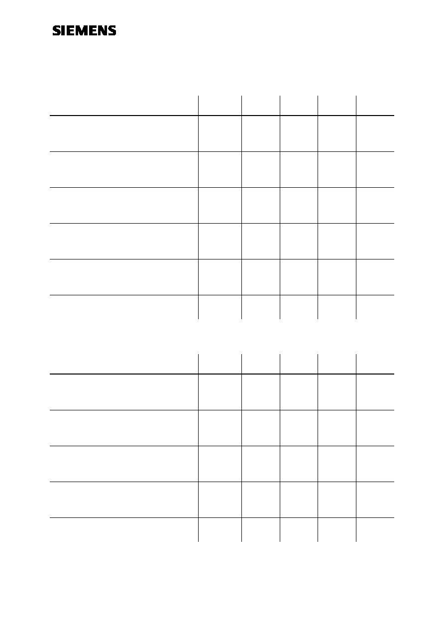
900MHz measurement and application circuit (Figure 1)
printed
inductor
1nF
2)
LO in
1nF
IF out
Udc=3V
3)
1)
100pF
470nH
680Ohms
RF in
33pF
47pF
45MHz
4.7pF
27nH
920MHz
965MHz
1) Siemens SIMID 01-coil; Ordering code: B82412-A3270-M
2) Optional resistor increases IF-amplifier operating current and improves
conversion gain and intermodulation performance
(minimum value: 27
)
3) Siemens SIMID 01-coil; Ordering code: B82412-A3471-K
GaAs MMIC
CMY 91
________________________________________________________________________________________________________
Siemens Aktiengesellschaft
pg. 6/9
16.12.96
HL EH PD21
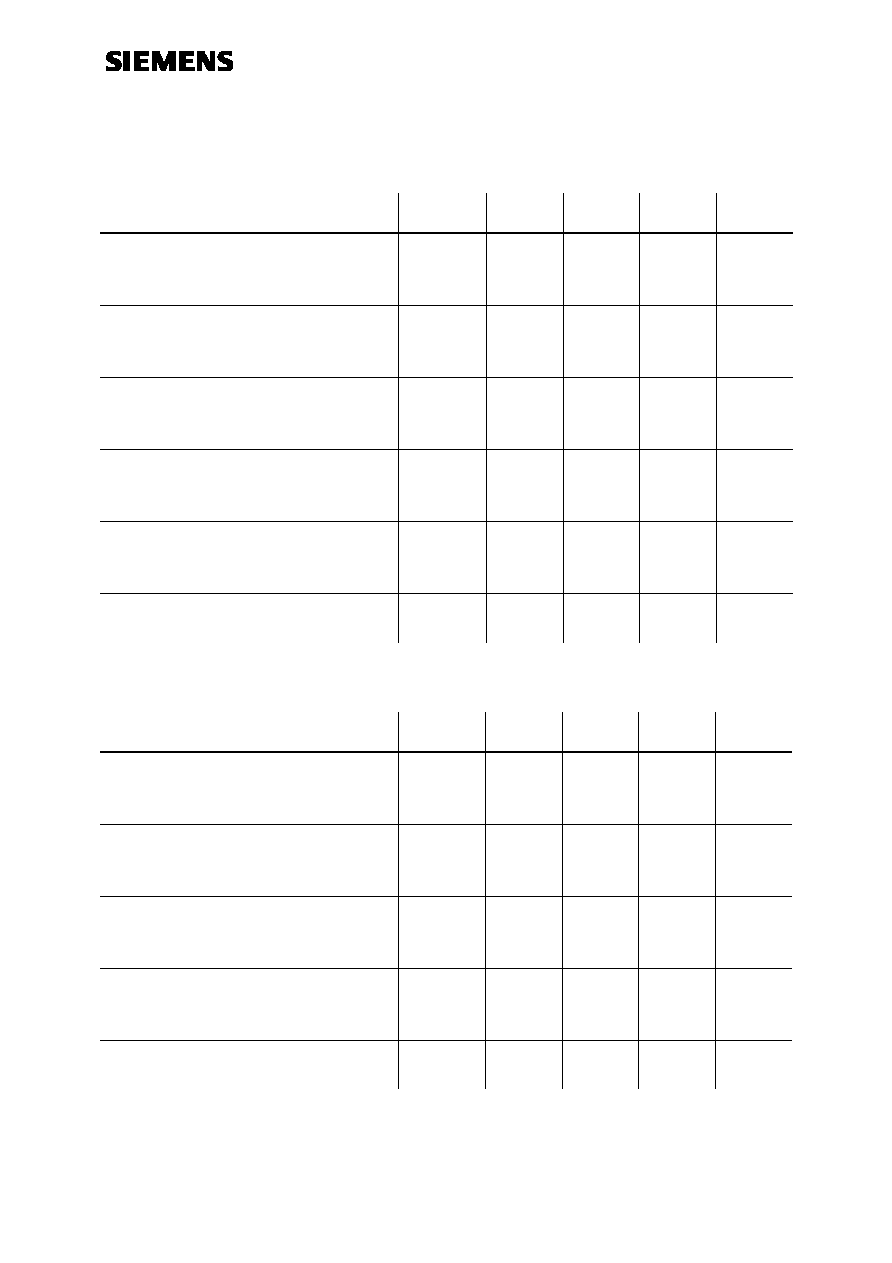
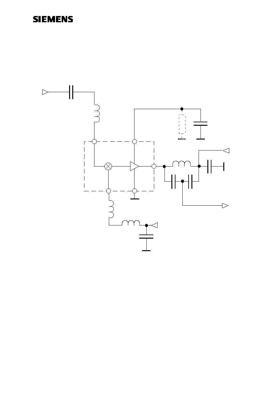
1450MHz measurement and application circuit (Figure 2)
printed
inductor
1nF
2)
LO in
1nF
IF out
Udc=3V
3)
1)
100pF
680Ohms
RF in
1450MHz
1350MHz
3.3nH
printed
inductor
220nH
3.3pF
100MHz
15pF 18pF
1)
1) Tune for optimum match
2) Optional resistor increases IF-amplifier operating current and improves
conversion gain and intermodulation performance
(minimum value: 27
)
3) Siemens SIMID 01-coil; Ordering code: B82412-A3221-K

GaAs MMIC
CMY 91
________________________________________________________________________________________________________
Siemens Aktiengesellschaft
pg. 7/9
16.12.96
HL EH PD21
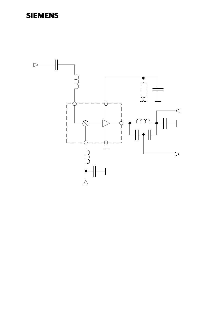
1900MHz measurement and application circuit (Figure 1)
printed
inductor
1nF
2)
LO in
1nF
IF out
Udc=3V
1)
100pF
680Ohms
RF in
printed
inductor
220nH
100MHz
15pF
18pF
1900MHz
2.2pF
1800MHz
1)
3)
1) Tune for optimum match
2) Optional resistor increases IF-amplifier operating current and improves
conversion gain and intermodulation performance
(minimum value: 27
)
3) Siemens SIMID 01-coil; Ordering code: B82412-A3221-M

GaAs MMIC
CMY 91
________________________________________________________________________________________________________
Siemens Aktiengesellschaft
pg. 8/9
16.12.96
HL EH PD21
PCB - Layouts for Application Circuits
900MHz - application board:
LO
IF
RF
CMY91
4.7pF
1nF
100pF
470nH
47pF
33pF
LO
IF
RF
CMY91
Actual size
20mm
◊
20mm
1450MHz - application board:
LO
IF
RF
CMY91
3.3pF
220nH
1nF
15pF
18pF
100pF
s oldered s horting line for tuning the LO-match
LO
IF
RF
CMY91
Actual size
20mm
◊
20mm
PCB - data: Glass fiber epoxy board (double sided)
r
= 4.8 thickness = 1mm

GaAs MMIC
CMY 91
________________________________________________________________________________________________________
Siemens Aktiengesellschaft
pg. 9/9
16.12.96
HL EH PD21
1900MHz - application board:
s oldered s horting line for tuning the LO-match
LO
IF
RF
CMY91
2.2pF
220nH
1nF
18pF
15pF
100pF
LO
IF
RF
CMY91
Actual size
20mm
◊
20mm
PCB - data: Glass fiber epoxy board (double sided)
r
= 4.8 thickness = 1mm