
Semiconductor Group
1
1997-11-01
GaAs-IR-Lumineszenzdiode
GaAs Infrared Emitter
Wesentliche Merkmale
q
GaAs-IR-LED, hergestellt im
Schmelzepitaxieverfahren
q
Hohe Zuverl‰ssigkeit
q
Hohe Impulsbelastbarkeit
q
Lange Anschl¸sse
q
Gruppiert lieferbar
q
Geh‰usegleich mit SFH 300, SFH 203
Anwendungen
q
IR-Fernsteuerung von Fernseh- und
Rundfunkger‰ten, Videorecordern,
Lichtdimmern
q
Ger‰tefernsteuerungen
q
Lichtschranken f¸r Gleich- und
Wechsellichtbetrieb
Features
q
GaAs infrared emitting diode, fabricated in a
liquid phase epitaxy process
q
High reliability
q
High pulse handling capability
q
long leads
q
Available in groups
q
Same package as SFH 300, SFH 203
Applications
q
IR remote control of hi-fi and TV-sets, video
tape recorders, dimmers
q
Remote control of various equipment
q
Photointerrupters
LD 271, LD 271 H
LD 271 L, LD 271 HL
Maþe in mm, wenn nicht anders angegeben/Dimensions in mm, unless otherwise specified.
fex06628
7.8
7.5
9.0
8.2
29
27
1.8
1.2
4.8
4.2
¯5.1
¯4.8
0.8
0.4
0.6
0.4
2.54mm
spacing
5.9
5.5
0.6
0.4
Area not flat
Chip position
Cathode
Approx. weight 0.2 g
GEO06645
5.9
5.5
0.6
0.4
¯5.1
¯4.8
2.54 mm
spacing
7.8
7.5
9.0
8.2
4.8
4.2
11.4
11.0
14.0
13.0
1.8
1.2
1.3
1.0
Area not flat
0.6
0.4
Cathode
Chip position
GEX06239
Approx. weight 0.5 g
1.0
0.7
Semiconductor Group
2
1997-11-01
LD 271, LD 271 H
LD 271 L, LD 271 HL
Grenzwerte
Maximum Ratings
Typ
Type
Bestellnummer
Ordering Code
Geh‰use
Package
LD 271
Q62703-Q148
5-mm-LED-Geh‰use (T 1
3
/
4
), graugetˆntes Epoxy-
Gieþharz, Lˆtspieþe im 2.54-mm-Raster (
1
/
10
'')
5 mm LED package (T 1
3
/
4
), grey colored epoxy resin
lens, solder tabs lead spacing 2.54 mm (
1
/
10
'')
LD 271 L
Q62703-Q833
LD271 H
Q62703-Q256
LD271 HL
Q62703-Q838
Bezeichnung
Description
Symbol
Symbol
Wert
Value
Einheit
Unit
Betriebs- und Lagertemperatur
Operating and storage temperature range
T
op
;
T
stg
≠ 55 ... + 100
∞
C
Sperrschichttemperatur
Junction temperature
T
j
100
∞
C
Sperrspannung
Reverse voltage
V
R
5
V
Durchlaþstrom
Forward current
I
F
130
mA
Stoþstrom,
t
p
= 10
µ
s,
D
= 0
Surge current
I
FSM
3.5
A
Verlustleistung
Power dissipation
P
tot
220
mW
W‰rmewiderstand
Thermal resistance
R
thJA
330
K/W

LD 271, LD 271 H
LD 271 L, LD 271 HL
Semiconductor Group
3
1997-11-01
Kennwerte (
T
A
= 25
∞
C)
Characteristics
Bezeichnung
Description
Symbol
Symbol
Wert
Value
Einheit
Unit
Wellenl‰nge der Strahlung
Wavelength at peak emission
I
F
= 100 mA,
t
p
= 20 ms
peak
950
nm
Spektrale Bandbreite bei 50 % von
I
max
Spectral bandwidth at 50 % of
I
max
I
F
= 100 mA
55
nm
Abstrahlwinkel
Half angle
±
25
Grad
deg.
Aktive Chipfl‰che
Active chip area
A
0.25
mm
2
Abmessungen der aktive Chipfl‰che
Dimensions of the active chip area
L
◊
B
L
◊
W
0.5
◊
0.5
mm
Abstand Chipoberfl‰che bis Linsenscheitel
Distance chip front to lens top
H
4.0 ... 4.6
mm
Schaltzeiten,
I
e
von 10 % auf 90 % und von
90 % auf 10 %, bei
I
F
= 100 mA,
R
L
= 50
Switching times,
I
e
from 10 % to 90 % and
from 90 % to 10 %,
I
F
= 100 mA,
R
L
= 50
t
r
,
t
f
1
µ
s
Kapazit‰t,
V
R
= 0 V,
f
= 1 MHz
Capacitance
C
o
40
pF
Durchlaþspannung
Forward voltage
I
F
= 100 mA,
t
p
= 20 ms
I
F
= 1 A,
t
p
= 100
µ
s
V
F
V
F
1.30
(
1.5)
1.90
(
2.5
)
V
V
Sperrstrom,
V
R
= 5 V
Reverse current
I
R
0.01
(
1
)
µ
A
Gesamtstrahlungsfluþ
Total radiant flux
I
F
= 100 mA,
t
p
= 20 ms
e
18
mW
Temperaturkoeffizient von
I
e
bzw.
e
,
I
F
= 100 mA
Temperature coefficient of
I
e
or
e
,
I
F
= 100 mA
TC
I
≠ 0.55
%/K
Temperaturkoeffizient von
V
F
,
I
F
= 100 mA
Temperature coefficient of
V
F
,
I
F
= 100 mA
TC
V
≠ 1.5
mV/K
Temperaturkoeffizient von
,
I
F
= 100 mA
Temperature coefficient of
,
I
F
= 100 mA
TC
0.3
nm/K
Semiconductor Group
4
1997-11-01
LD 271, LD 271 H
LD 271 L, LD 271 HL
Gruppierung der Strahlst‰rke
I
e
in Achsrichtung
gemessen bei einem Raumwinkel
= 0.01 sr
Grouping of radiant intensity
I
e
in axial direction
at a solid angle of
= 0.01 sr
Bezeichnung
Description
Symbol
Symbol
Wert
Value
Einheit
Unit
LD 271
LD 271 L
LD 271 H
LD 271 HL
Strahlst‰rke
Radiant intensity
I
F
= 100 mA,
t
p
= 20 ms
I
F
= 1 A,
t
p
= 100
µ
s
I
e
I
e typ.
15 (
10)
120
> 16
mW/sr
mW/sr
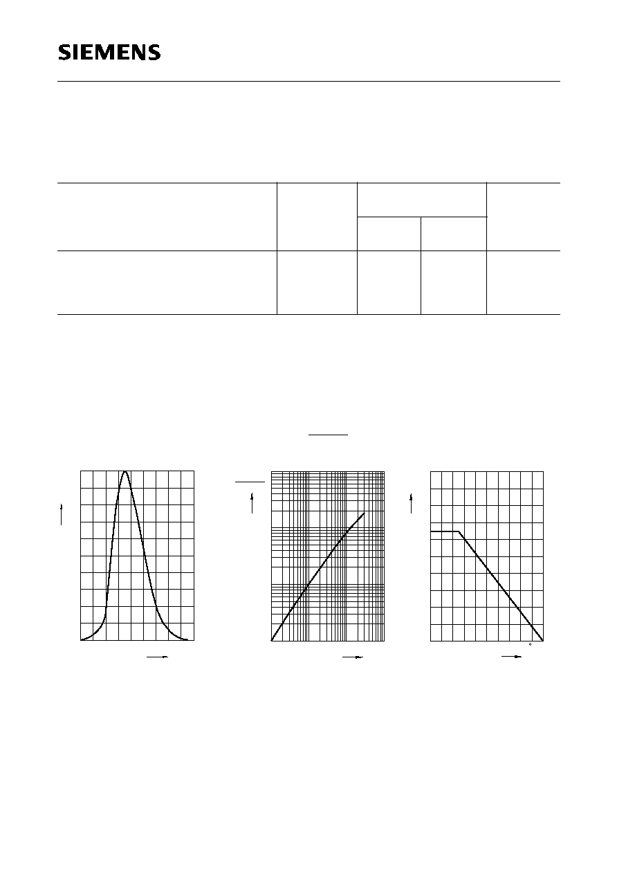
Relative spectral emission
I
rel
=
f
(
)
OHRD1938
rel
0
880
920
960
1000
nm
1060
20
40
60
80
%
100
Radiant intensity
Single pulse,
t
p
= 20
µ
s
I
e
I
e
100 mA
=
f
(
I
F
)
OHR01038
F
-1
10
10
0
1
10
2
10
10
-2
-1
10
0
10
A
10
1
e
e
(100 mA)
Max. permissible forward current
I
F
=
f
(
T
A
)
T
OHO00364
A
0
F
0
20
40
60
80
100
C
mA
20
40
60
80
100
120
140
160
200
LD 271, LD 271 H
LD 271 L, LD 271 HL
Semiconductor Group
5
1997-11-01
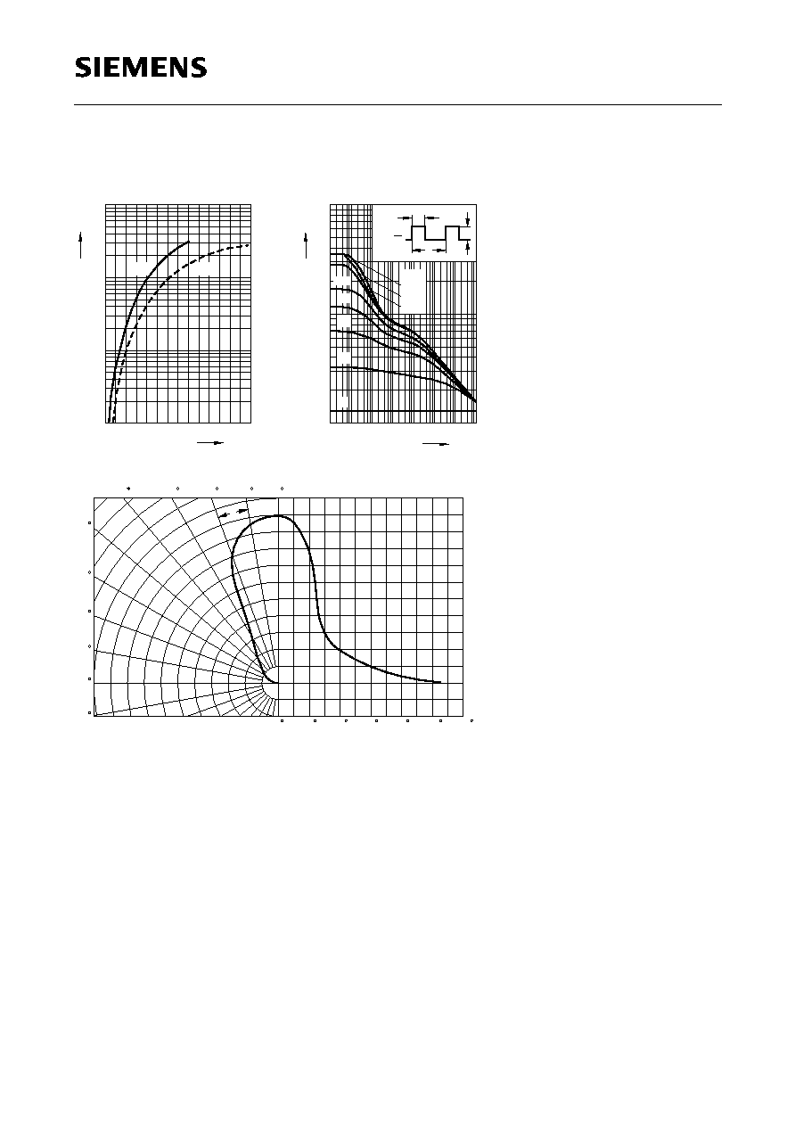
Forward current
I
F
=
f
(
V
F
), single pulse,
t
p
= 20
µ
s
V
OHR01041
F
F
1
1
10
0
10
-1
10
10
-2
A
1.5
2
2.5
3
3.5
4 V 4.5
max.
typ.
Permissible pulse handling capability
I
F
=
f
(
),
T
C
= 25
∞
C,
duty cycle
D
= parameter
t
OHR00257
P
10
-5
s
T
t
p
D
=
t
p
T
F
10
4
F
DC
0.5
0.2
0.1
0.005
0.01
0.02
0.05
mA
10
3
10
2
-4
10
-3
10
-2
10
-1
10
0
10
2
10
=
D
5
5
Radiation characteristics
I
rel
=
f
(
)
OHR01879
0
20
40
60
80
100
120
0.4
0.6
0.8
1.0
100
90
80
70
60
50
0
10
20
30
40
0
0.2
0.4
0.6
0.8
1.0