Semiconductor Group
1
11.96
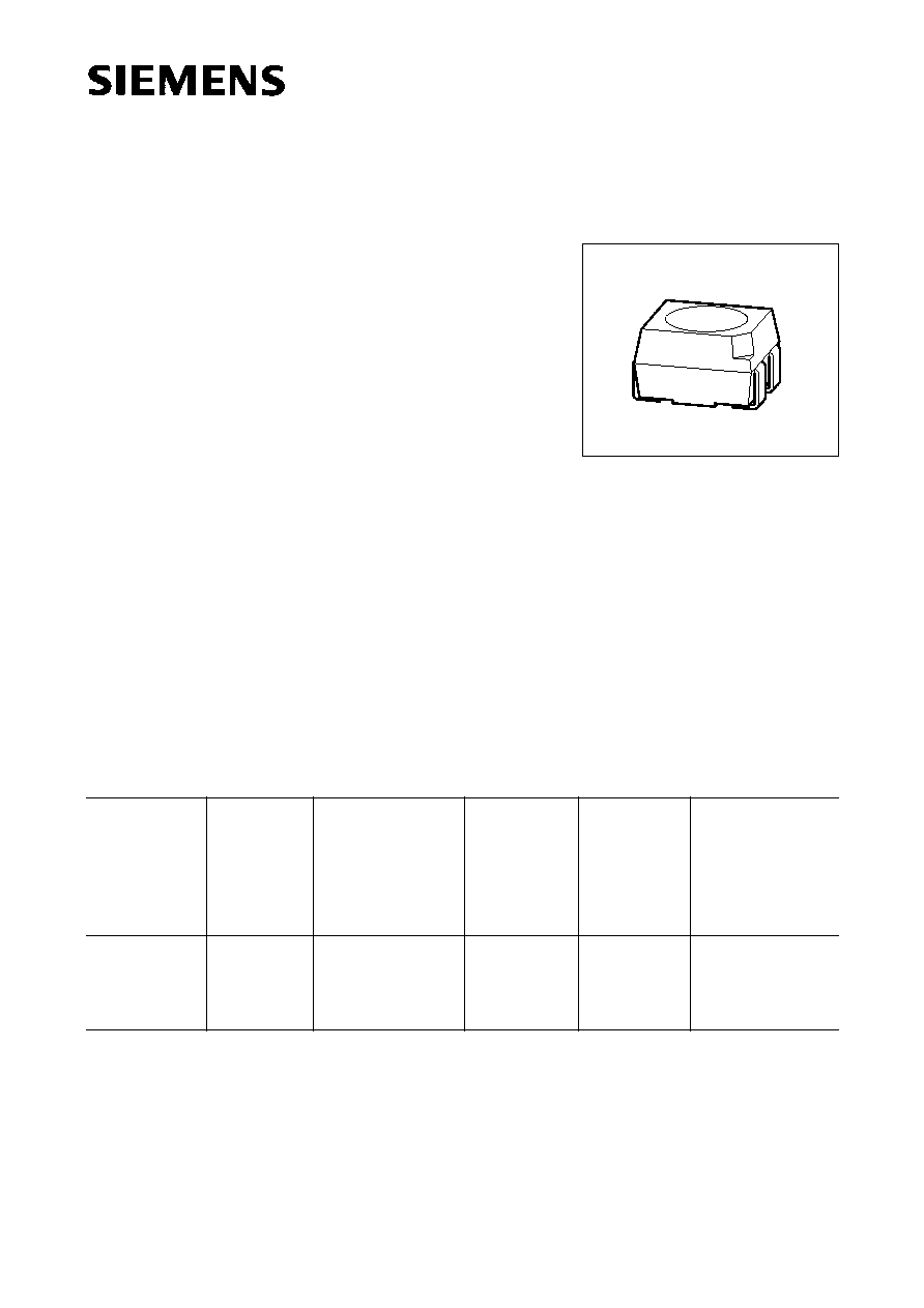
Multi TOPLED
ģ
Cathodes On One Side
LSG T677
Besondere Merkmale
q
Gehšusebauform: P-LCC-4
q
Gehšusefarbe: weiŖ
q
als optischer Indikator einsetzbar
q
zur Hinterleuchtung, Lichtleiter- und Linseneinkopplung
q
beide Leuchtdiodenchips getrennt ansteuerbar
q
hohe Signalwirkung durch Farbwechsel der LED mŲglich
q
bei geeigneter Ansteuerung, Farbwechsel von grŁn Łber
gelb und orange bis super-rot mŲglich
q
fŁr alle SMT-BestŁck- und LŲttechniken geeignet
q
gegurtet (8-mm-Filmgurt)
q
StŲrimpulsfest nach DIN 40839
Features
q
P-LCC-4 package
q
color of package: white
q
for use as optical indicator
q
for backlighting, optical coupling into light pipes and lenses
q
both chips can be controlled separately
q
high signal efficiency possible by color change of the LED
q
with appropriate controlling it is possible to change color from
green to yellow and orange to super-red
q
suitable for all SMT assembly and soldering methods
q
available taped on reel (8 mm tape)
q
load dump resistant acc. to DIN 40839
Streuung der Lichtstšrke in einer Verpackungseinheit
I
V max
/
I
V min
2.0.
1)
Streuung der Lichtstšrke in einer LED
I
V max
/
I
V min
3.0.
1)
Bei MULTILED
ģ
bestimmt die Helligkeit des jeweils dunkleren Chips in einem Gehšuse die Helligkeitsgruppe
der LED.
Luminous intensity ratio in one packaging unit
I
V max
/
I
V min
2.0.
1)
Luminous intensity ratio in one LED
I
V max
/
I
V min
3.0.
1)
In case of MULTILED
ģ
, the brightness of the darker chip in one package determines the brightness group of
the LED.
Typ
Type
Emissions-
farbe
Color of
Emission
Farbe der Licht-
austrittsflšche
Color of the
Light Emitting
Area
Lichtstšrke
Luminous
Intensity
I
F
= 10 mA
I
V
(mcd)
Lichtstrom
Luminous
Flux
I
F
= 10 mA
V
(mlm)
Bestellnummer
Ordering Code
LSG T677-HK
LSG T677-J
LSG T677-K
LSG T677-JL
super-red /
green
colorless clear
2.5 ... 12.5
4.0 ... 8.0
6.3 ... 12.5
4.0 ... 20.0
-
18 (typ.)
30 (typ.)
-
Q62703-Q3370
Q62703-Q3371
Q62703-Q3372
Q62703-Q3373
VPL06837

Semiconductor Group
2
LSG T677
Grenzwerte
Maximum Ratings
Bezeichnung
Parameter
Symbol
Symbol
Wert
Value
Einheit
Unit
Betriebstemperatur
Operating temperature range
T
op
≠ 55 ... + 100
įC
Lagertemperatur
Storage temperature range
T
stg
≠ 55 ... + 100
įC
Sperrschichttemperatur
Junction temperature
T
j
+ 100
įC
DurchlaŖstrom
Forward current
I
F
30
mA
StoŖstrom
Surge current
t
10
Ķ
s,
D
= 0.005
I
FM
0.5
A
Sperrspannung
Reverse voltage
V
R
5
V
Verlustleistung
Power dissipation
P
tot
100
mW
Wšrmewiderstand
Thermal resistance
Sperrschicht / Umgebung
Junction / air
Montage auf PC-Board*
)
(PadgrŲŖe
16 mm
2
)
mounted on PC board*
)
(pad size
16 mm
2
)
R
th JA
1)
R
th JA
2)
480
650
K/W
K/W
*
)
PC-board: FR4
1)
nur ein Chip betrieben
1)
one system on
2)
beide Chips betrieben
2)
both systems on simultaneously
Notes
Die angegebenen Grenzdaten gelten fŁr einen Chip.
The stated maximum ratings refer to one chip.
Semiconductor Group
3
LSG T677
Kennwerte (
T
A
= 25 įC)
Characteristics
Bezeichnung
Parameter
Symbol
Symbol
Wert
Value
Ein-
heit
Unit
LS
LG
Wellenlšnge des emittierten Lichtes (typ.)
Wavelength at peak emission (typ.)
I
F
= 10 mA
peak
635
565
nm
Dominantwellenlšnge (typ.)
Dominant wavelength (typ.)
I
F
= 10 mA
dom
628
570
nm
Spektrale Bandbreite bei 50 %
I
rel max
(typ.)
Spectral bandwidth at 50 %
I
rel max
(typ.)
I
F
= 10 mA
45
25
nm
Abstrahlwinkel bei 50 %
I
V
(Vollwinkel)
Viewing angle at 50 %
I
V
2
120
120
Grad
deg.
DurchlaŖspannung (typ.)
Forward voltage (max.)
I
F
= 10 mA
V
F
V
F
2.0
2.6
2.0
2.6
V
V
Sperrstrom (typ.)
Reverse current (max.)
V
R
= 5 V
I
R
I
R
0.01
10
0.01
10
Ķ
A
Ķ
A
Kapazitšt (typ.)
Capacitance
V
R
= 0 V,
f
= 1 MHz
C
0
12
15
pF
Schaltzeiten:
Switching times:
I
V
from 10 % to 90 % (typ.)
I
V
from 90 % to 10 % (typ.)
I
F
= 100 mA,
t
p
= 10
Ķ
s,
R
L
= 50
t
r
t
f
300
150
450
200
ns
ns

Semiconductor Group
4
LSG T677
Relative spektrale Emission
I
rel
=
f
(
),
T
A
= 25 įC,
I
F
= 10 mA
Relative spectral emission
V (
) = spektrale Augenempfindlichkeit
Standard eye response curve
Abstrahlcharakteristik
I
rel
=
f
(
)
Radiation characteristic
Semiconductor Group
5
LSG T677
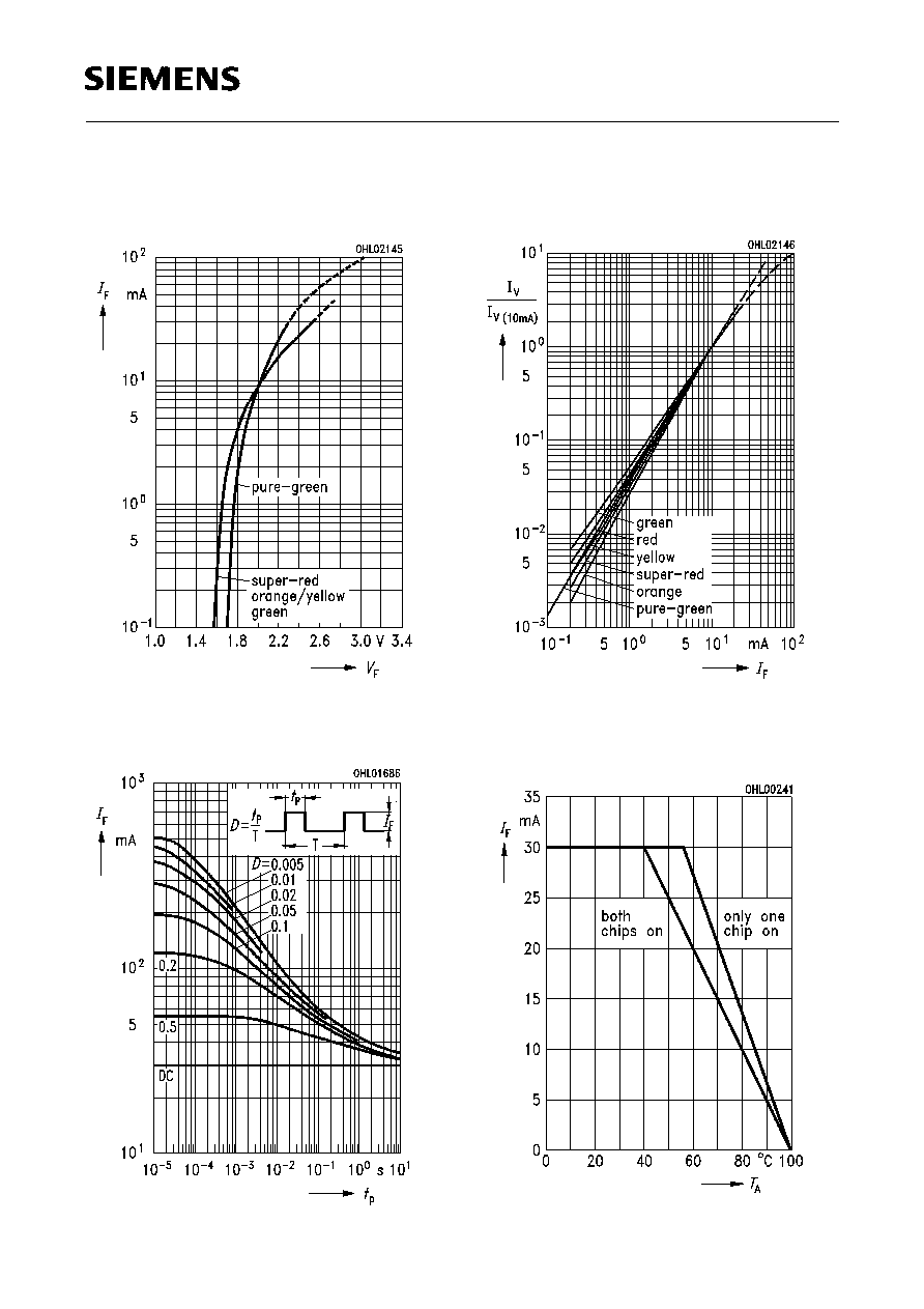
DurchlaŖstrom
I
F
=
f
(
V
F
)
Forward current
T
A
= 25 įC
Zulšssige Impulsbelastbarkeit
I
F
=
f
(
t
p
)
Permissible pulse handling capability
Duty cycle
D
= parameter,
T
A
= 25 įC
Relative Lichtstšrke
I
V
/
I
V(10 mA)
=
f
(
I
F
)
Relative luminous intensity
T
A
= 25 įC
Maximal zulšssiger DurchlaŖstrom
I
F
=
f
(
T
A
)
Max. permissible forward current

Semiconductor Group
6
LSG T677
Wellenlšnge der Stahlung
peak
=
f (T
A
)
Wavelength at peak emission
I
F
= 10 mA
DurchlaŖspannung
V
F
=
f
(
T
A
)
Forward voltage
I
F
= 10 mA
Dominantwellenlšnge
dom
=
f
(
T
A
)
Dominant wavelength
I
F
= 10 mA
Relative Lichtstšrke
I
V
/
I
V(25 įC)
=
f
(
T
A
)
Relative luminous intensity
I
F
= 10 mA
Semiconductor Group
7
LSG T677
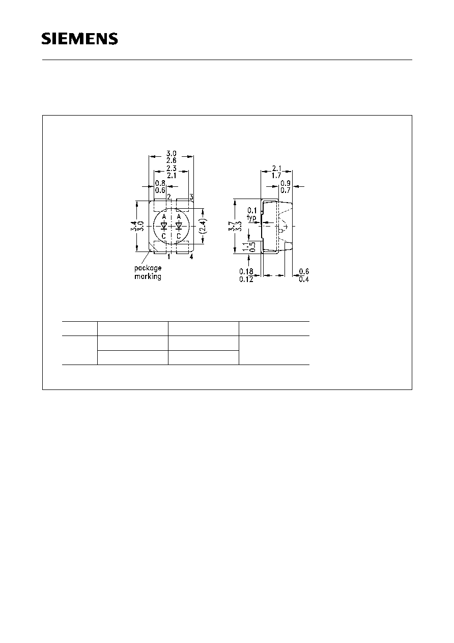
MaŖzeichnung
(MaŖe in mm, wenn nicht anders angegeben)
Package Outlines
(Dimensions in mm, unless otherwise specified)
GPL06925
L
S
G
T677
LED
Emission color 1 Emission color 2 Package
Cathode: pin 1
Cathode: pin 4