Semiconductor Group
1
11.96
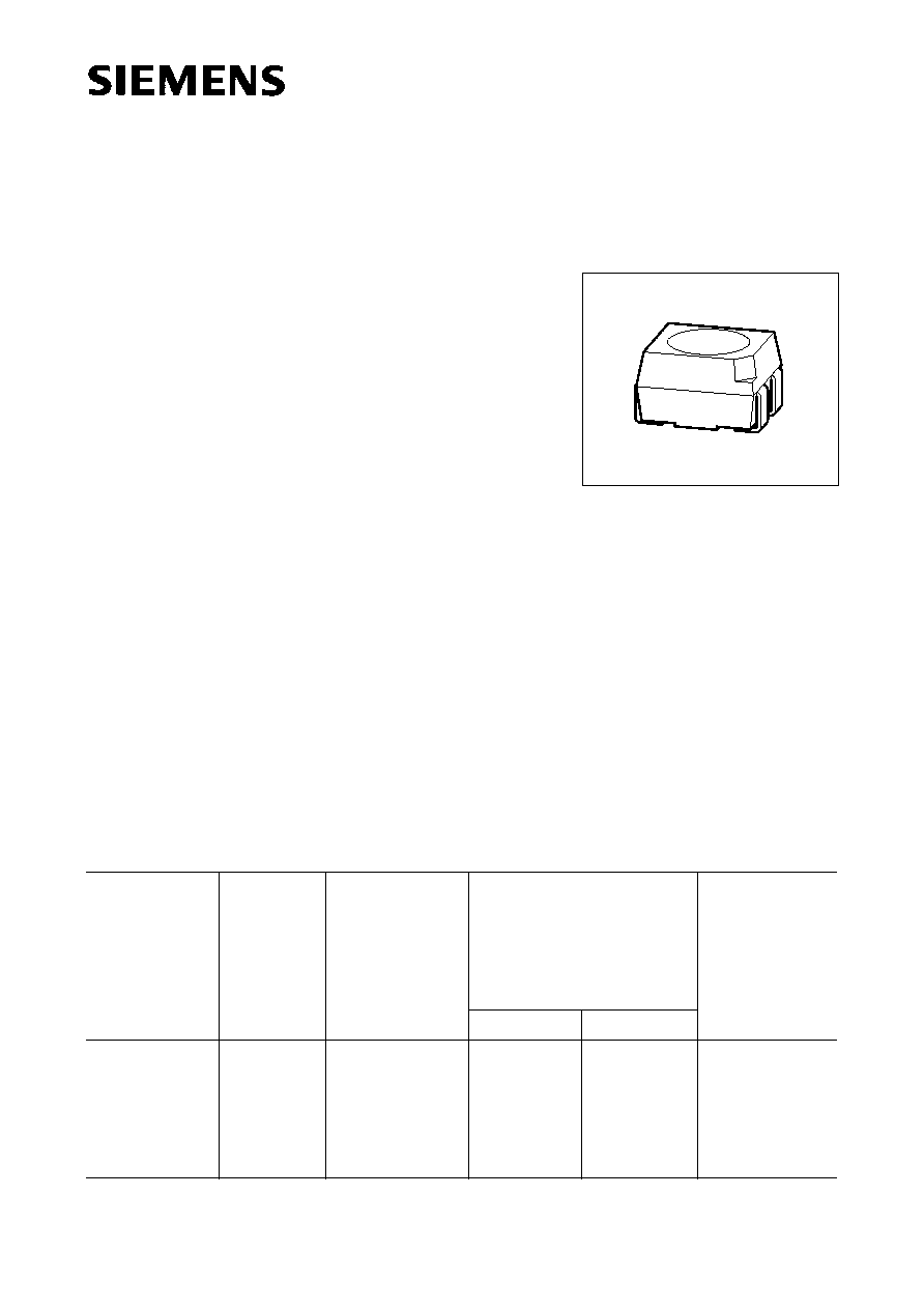
Hyper Multi TOPLED
Æ
Hyper-Bright LED
LSY T676
Besondere Merkmale
q
Geh‰usebauform: P-LCC-4
q
Geh‰usefarbe: weiþ
q
als optischer Indikator einsetzbar
q
zur Hinterleuchtung, Lichtleiter- und Linseneinkopplung
q
beide Leuchtdiodenchips getrennt ansteuerbar
q
hohe Signalwirkung durch Farbwechsel der LED mˆglich
q
bei geeigneter Ansteuerung, Farbwechsel von gr¸n ¸ber
gelb und orange bis super-rot mˆglich
q
f¸r alle SMT-Best¸ck- und Lˆttechniken geeignet
q
gegurtet (8-mm-Filmgurt)
q
Stˆrimpulsfest nach DIN 40839
Features
q
P-LCC-4 package
q
color of package: white
q
for use as optical indicator
q
for backlighting, optical coupling into light pipes and lenses
q
both chips can be controlled separately
q
high signal efficiency possible by color change of the LED
q
with appropriate controlling it is possible to change color
from green to yellow and orange to super-red
q
suitable for all SMT assembly and soldering methods
q
available taped on reel (8 mm tape)
q
load dump resistant acc. to DIN 40839
Typ
Type
Emissions-
farbe
Color of
Emission
Farbe der
Lichtaus-
trittsfl‰che
Color of the
Light Emitting
Area
Lichtst‰rke
Luminous Intensity
I
F
= 20 mA
I
V
(mcd)
Bestellnummer
Ordering Code
super-red
yellow
LSY T676
LSY T676-P+P
LSY T676-P+Q
LSY T676-P+R
LSY T676-Q+Q
LSY T676-Q+R
super-red /
yellow
colorless clear
40
40 ... 80
40 ... 80
40 ... 80
63 ... 125
63 ... 125
40
40 ... 80
63 ... 125
100 ... 200
63 ... 125
100 ... 200
Q62703-Q3428
VPL06837
Semiconductor Group
2
LSY T676
Grenzwerte
Maximum Ratings
Bezeichnung
Parameter
Symbol
Symbol
Wert
Value
Einheit
Unit
LS
LY
Betriebstemperatur
Operating temperature range
T
op
≠ 55 ... + 100
∞C
Lagertemperatur
Storage temperature range
T
stg
≠ 55 ... + 100
∞C
Sperrschichttemperatur
Junction temperature
T
j
+ 100
∞C
Durchlaþstrom
Forward current
I
F
30
20
mA
Stoþstrom
Surge current
t
10
µ
s,
D
= 0.005
I
FM
to be defined
A
Sperrspannung
Reverse voltage
V
R
3
V
Verlustleistung
Power dissipation
P
tot
80
55
mW
W‰rmewiderstand
Thermal resistance
Sperrschicht / Umgebung
Junction / air
Montage auf PC-Board*
)
(Padgrˆþe
16 mm
2
)
mounted on PC board*
)
(pad size
16 mm
2
)
R
th JA
1)
R
th JA
2)
500
600
K/W
K/W
*
)
PC-board: FR4
1)
nur ein Chip betrieben
1)
one system only
2)
beide Chips betrieben
2)
both systems on simultaneously
Notes
Die angegebenen Grenzdaten gelten f¸r einen Chip.
The stated maximum ratings refer to one chip.
Semiconductor Group
3
LSY T676
Kennwerte (
T
A
= 25 ∞C)
Characteristics
Bezeichnung
Parameter
Symbol
Symbol
Wert
Value
Ein-
heit
Unit
LS
LY
Wellenl‰nge des emittierten Lichtes
(typ.)
Wavelength at peak emission
(typ.)
I
F
= 10 mA
peak
645
591
nm
Dominantwellenl‰nge
(typ.)
Dominant wavelength
(typ.)
I
F
= 10 mA
dom
630
587
nm
Spektrale Bandbreite bei 50 %
I
rel max
(typ.)
Spectral bandwidth at 50 %
I
rel max
(typ.)
I
F
= 10 mA
16
15
nm
Abstrahlwinkel bei 50 %
I
V
(Vollwinkel)
Viewing angle at 50 %
I
V
2
120
120
Grad
deg.
Durchlaþspannung
(typ.)
Forward voltage
(max.)
I
F
= 20 mA
V
F
V
F
2.0
2.6
2.0
2.6
V
V
Sperrstrom
(typ.)
Reverse current
(max.)
V
R
= 3 V
I
R
I
R
0.01
10
0.01
10
µ
A
µ
A
Temperaturkoeffizient von
dom
(
I
F
= 20 mA)
Temperature coefficient of
dom
(
I
F
= 20 mA)
TC
0.014
0.096
nm/K
Temperaturkoeffizient von
peak
,
I
F
= 20 mA
(typ.)
Temperature coefficient of
peak
,
I
F
= 20 mA
(typ.)
TC
0.14
0.13
nm/K
Temperaturkoeffizient von
V
F
, I
F
= 20 mA
(typ.)
Temperature coefficient of
V
F
, I
F
= 20 mA
(typ.)
TC
V
≠ 1.95
≠ 2.51
mV/K
Semiconductor Group
4
LSY T676
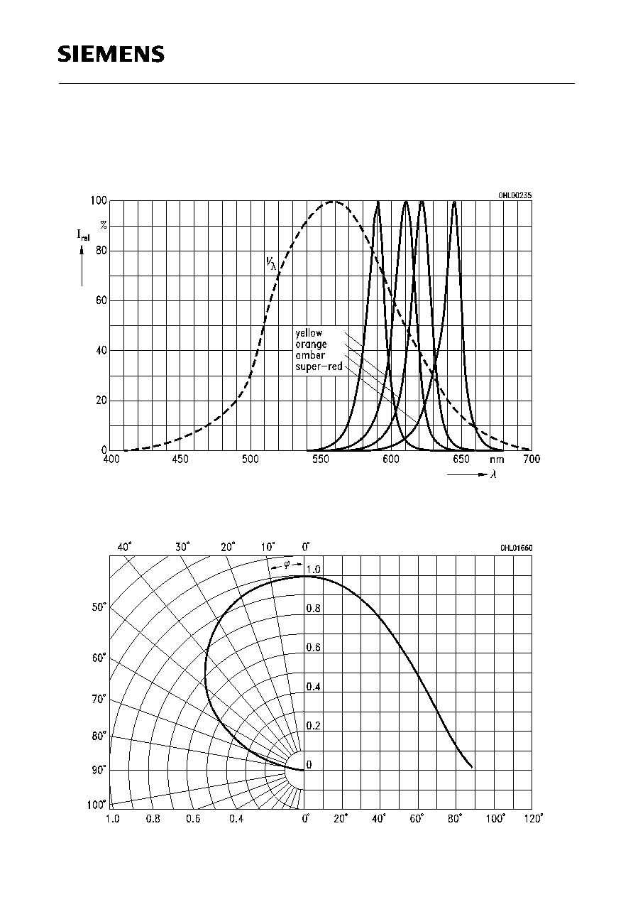
Relative spektrale Emission
I
rel
=
f
(
),
T
A
= 25 ∞C,
I
F
= 10 mA
Relative spectral emission
V (
) = spektrale Augenempfindlichkeit
Standard eye response curve
Abstrahlcharakteristik
I
rel
=
f
(
)
Radiation characteristic
Semiconductor Group
5
LSY T676
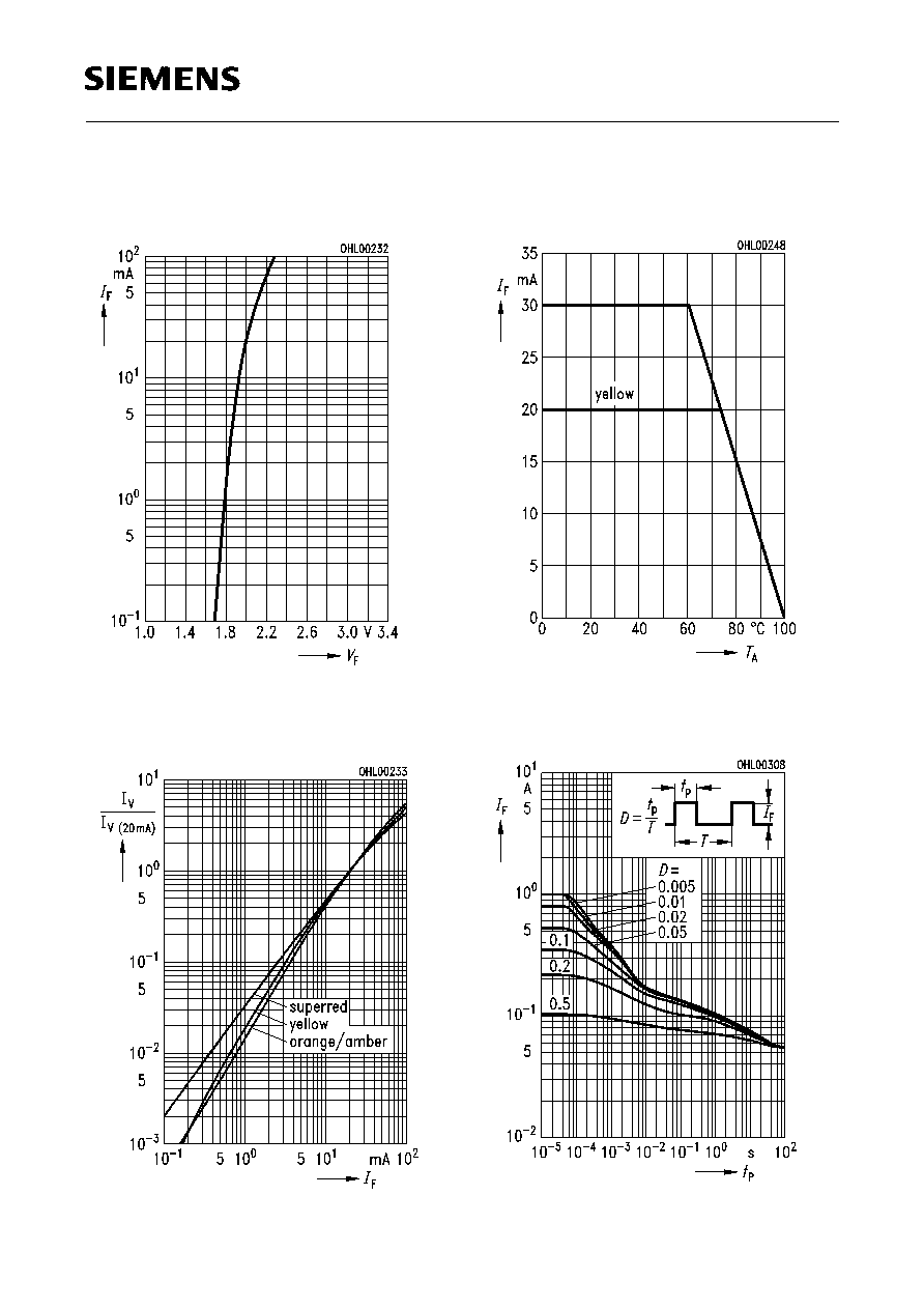
Durchlaþstrom
I
F
=
f
(
V
F
)
Forward current
T
A
= 25 ∞C
Relative Lichtst‰rke
I
V
/
I
V(20 mA)
=
f
(
I
F
)
Relative luminous intensity
T
A
= 25 ∞C
Maximal zul‰ssiger Durchlaþstrom
I
F
=
f
(
T
A
)
Max. permissible forward current
Zul‰ssige Impulsbelastbarkeit
I
f
=
f
(
t
p
)
Permissible pulse handling capability
D
= Parameter;
T
A
= 25
∞
C
Semiconductor Group
6
LSY T676
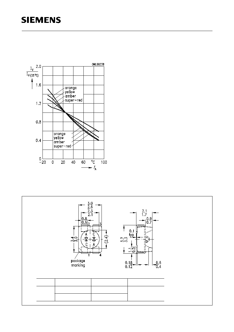
Relative Lichtst‰rke
I
V
/
I
V(25 ∞C)
=
f
(
T
A
)
Relative luminous intensity
I
F
= 10 mA
Maþzeichnung
(Maþe in mm, wenn nicht anders angegeben)
Package Outlines
(Dimensions in mm, unless otherwise specified)
GPL06837
L
S
Y
T676
LED
Emission color 1 Emission color 2 Package
cathode: pin 1
cathode: pin 3