 | –≠–ª–µ–∫—Ç—Ä–æ–Ω–Ω—ã–π –∫–æ–º–ø–æ–Ω–µ–Ω—Ç: STAC9463 | –°–∫–∞—á–∞—Ç—å:  PDF PDF  ZIP ZIP |

Integrating Mixed-Signal Solutions
Copyright © 2002 SigmaTel, Inc. All rights reserved.
All contents of this document are protected by copyright law and may not be reproduced without the express written consent of SigmaTel, Inc.
I
2
C is a registered trademark of Philips Semiconductor and requires a license for use of the I
2
C bus interface.
SigmaTel, the SigmaTel logo, and combinations thereof are trademarks of SigmaTel, Inc. Other product names used in this publication are
for identification purposes only and may be trademarks or registered trademarks of their respective companies. The contents of this docu-
ment are provided in connection with SigmaTel, Inc. products. SigmaTel, Inc. has made best efforts to ensure that the information contained
herein is accurate and reliable. However, SigmaTel, Inc. makes no warranties, express or implied, as to the accuracy or completeness of
the contents of this publication and is providing this publication "AS IS". SigmaTel, Inc. reserves the right to make changes to specifications
and product descriptions at any time without notice, and to discontinue or make changes to its products at any time without notice. SigmaTel,
Inc. does not assume any liability arising out of the application or use of any product or circuit, and specifically disclaims any and all liability,
including without limitation special, consequential, or incidential damages.
PRELIMINARY DATA SHEET
STAC9461/63
Two and Six-Channel, 24-Bit, 192 kHz
Audio DAC
Two and Six-Channel, 24-Bit, 192 kHz
Audio DAC
PRELIMINARY INFORMATION 1/24/02
2-9461-D1-2.0-0102

2
2-9461-D1-2.0-0102
STAC9461/63
Two and Six-Channel, 24-Bit, 192 kHz Audio DAC
P R E L I M I N A R Y I N F O R M A T I O N 1 / 2 4 / 0 2
1. TABLE OF CONTENTS
1. TABLE OF CONTENTS ............................................................................................................. 2
1.1. List of Figures ....................................................................................................................................3
1.2. List of Tables ......................................................................................................................................3
2. PRODUCT BRIEF ...................................................................................................................... 4
2.1. FEATURES ........................................................................................................................................4
2.2. Ordering Information ..........................................................................................................................4
2.3. Block Diagrams ..................................................................................................................................5
2.4. Related Materials ...............................................................................................................................5
2.5. Additional Support ..............................................................................................................................5
3. CHARACTERISTICS AND SPECIFICATIONS ......................................................................... 6
3.1. Absolute Maximum Ratings ...............................................................................................................6
3.2. Recommended Operating Conditions ..............................................................................................6
3.3. Power Consumption .........................................................................................................................6
3.4. Static Digital Specifications ................................................................................................................6
3.5. STAC9461 Analog Performance Characteristics ...............................................................................7
4. STAC9461 TYPICAL CONNECTION DIAGRAM ...................................................................... 8
5. STAC9463 TYPICAL CONNECTION DIAGRAM ...................................................................... 9
6. SERIAL INTERFACE ............................................................................................................... 10
6.1. Clocking ...........................................................................................................................................10
6.2. Reset ................................................................................................................................................10
7. DIGITAL AUDIO INTERFACE ................................................................................................ 11
7.1. I2S Serial Interface ..........................................................................................................................11
7.2. Single Line Format ..........................................................................................................................12
7.3. I2C-Bus Interface .............................................................................................................................12
8. PROGRAMMABILITY .............................................................................................................. 14
8.1. List of Registers ...............................................................................................................................15
8.1.1. Reset/Status Register (00h) ...............................................................................................15
8.1.2. Status Register (01h) .........................................................................................................15
8.1.3. Master Volume Register (02h) ...........................................................................................15
8.1.4. LF/RF, LR/RR, Center/LFE Output Channel Volume Registers(03h-08h) .........................16
8.1.5. Reserved Registers (09h-0Bh) ...........................................................................................16
8.1.6. De-Emphasis Register (0Ch) ............................................................................................16
8.1.7. Reserved Register (0Dh) ...................................................................................................16
8.1.8. Audio Port Control (0Eh) ....................................................................................................17
8.1.9. The Master Clocking Register (0Fh) ..................................................................................17
8.1.10. Powerdown Control Registers (10h-11h) .........................................................................18
8.1.11. Revision Code Register (12h) ..........................................................................................18
8.1.12. Address Control Register/Address Register (13h-14h) ....................................................18
9. PIN DESCRIPTION .................................................................................................................. 19
9.1. Six Channel STAC9461 Pin and Signal Description ........................................................................19
9.2. Two Channel STAC9463 Pin and Signal Description ......................................................................19
9.3. Digital I/O .........................................................................................................................................20
9.4. Analog I/O ........................................................................................................................................20
9.5. Filter/References ..............................................................................................................................20
9.6. Power and Ground Signals ..............................................................................................................20
10. PACKAGE DRAWING ........................................................................................................... 21

2-9461-D1-2.0-0102
3
STAC9461/63
Two and Six-Channel, 24-Bit, 192 kHz Audio DAC
P R E L I M I N A R Y I N F O R M A T I O N 1 / 2 4 / 0 2
1.1.
List of Figures
Figure 1. STAC9461 & STAC9463 Block Diagram ..........................................................................................5
Figure 2. STAC9461 Typical Connection Diagram ..........................................................................................8
Figure 3. STAC9463 Typical Connection Diagram ..........................................................................................9
Figure 4. Serial interface to microcontroller or microprocessor ......................................................................10
Figure 5. STAC9461/63 I
2
S Format 1. ...........................................................................................................11
Figure 6. STAC9461/63 I
2
S Left Justified Format 1. ......................................................................................11
Figure 7. STAC9461/63 I
2
S Right Justified 16 Bit Format 1. .........................................................................11
Figure 8. STAC9461 Single Line 20 Bit Data Mode Timing Diagram .............................................................12
Figure 9. I
2
C Timing Diagram .........................................................................................................................12
Figure 10. STAC9461 Pin Designation .........................................................................................................19
Figure 11. STAC9463 Pin Designation ..........................................................................................................19
1.2.
List of Tables
Table 1. Digital Audio Interface Configuration ................................................................................................11
Table 2. Single Line 20 Bit Data Mode, Data Valid on Rising Edge of SCLK ................................................12
Table 3. I
2
C Mode Specifications ...................................................................................................................13
Table 4. Programming Registers ....................................................................................................................14
Table 5. Reset/Status Register ......................................................................................................................15
Table 6. Status Register .................................................................................................................................15
Table 7. Master Volume Register ...................................................................................................................15
Table 8. DAC Digital Volume Registers .........................................................................................................16
Table 9. On/Off De-emphasis Selection for Each Channel ............................................................................16
Table 10. De-emphasis Filter Selection .........................................................................................................16
Table 11. Audio Data Format Selection .........................................................................................................17
Table 12. Sample Rate Mode ........................................................................................................................17
Table 13. MCLK Mode ...................................................................................................................................17
Table 14. Powerdown Control ........................................................................................................................18
Table 15. Digital Signal List ............................................................................................................................20
Table 16. Analog Signal List ..........................................................................................................................20
Table 17. Filtering and Voltage References ...................................................................................................20
Table 18. Power Signal List ...........................................................................................................................20
4
2-9461-D1-2.0-0102
STAC9461/63
Two and Six-Channel, 24-Bit, 192 kHz Audio DAC
P R E L I M I N A R Y I N F O R M A T I O N 1 / 2 4 / 0 2
2. PRODUCT BRIEF
SigmaTel's STAC9461/63 are six and two-channel general-purpose 24-bit, audio
DACs for use in consumer applications. The STAC9461/63 incorporate SigmaTel's
proprietary Sigma-Delta technology to achieve DAC SNRs in excess of 100 dB.
There are three audio I
2
S inputs. The STAC9461/63 communicates via a standard
two-wire serial interface providing simplicity in the audio system design. Packaged
in a 28-pin SSOP, the STAC9461 and STAC9463 require minimal PCB space for
implementation. The STAC9461 and STAC9463 DACs are pin compatible with the
STAC9460 and STAC9462 audio codecs with integrated ADCs for recording.
The STAC9461 provides variable sample rate D-A converter, as well as analog pro-
cessing. Supported DAC audio sample rates include 32 kHz, 44.1 kHz, 48 kHz,
88.2 kHz, 96 kHz, 176.4 kHz and 192 kHz. The digital data interface communicates
via a standard I
2
C
Æ
compatible serial control interface and I
2
S digital audio inter-
face. All DAC's operate at 24-bit resolution with the sample rate based on the MCLK
and programmable registers.
The STAC9461/63 supports I
2
S digital audio inputs. These digital I/O options pro-
vide for a number of advanced architectural implementations, with volume controls
and mute capabilities built directly into the codec for each individual channel. The
output volume ranges from 0 dB to -95 dB with .75 dB steps. The STAC9461 also
supports a single-line format.
The STAC9461/63 is designed primarily to support 6-channel audio. True AC-3
playback can be achieved for 6-speaker applications by taking advantage of the
STAC9461 architecture and combining it with the appropriate processing. This
product is ideal for home theatre, DVD, karaoke, and set-top-box applications.
2.1.
FEATURES
∑
High performance
technology
∑
Two or six DAC channels with independent volume controls
∑
Master Volume Control for all DACs
∑
24-bit full duplex stereo DACs
∑
32, 44.1, 48, 88.2, 96, 176.4 and 192 kHz DAC sample rates
∑
Standard I
2
C
compatible and I
2
S serial interfaces
∑
Digital de-emphasis capability
∑
DAC SNR >104 dB normal 1V RMS mode
∑
AudioUltra
TM
Mode SNR 107dB with +3dBV output
∑
28-pin SSOP package
∑
Energy saving dynamic power modes
∑
5V Analog with 3.3V or 5V Digital capability
2.2.
Ordering Information
Note: SigmaTel reserves the right to change specifications without notice.
PART NUMBER
CHANNELS
PACKAGE
TEMPERATURE RANGE
SUPPLY RANGE
STAC9461S
6 DAC
28-pin SSOP
0
o
C to +70 ∫C
AVdd = 5V, DVdd = 3.3V or 5V
STAC9463S
2 DAC
28-pin SSOP
0
o
C to +70 ∫C
AVdd = 5V, DVdd = 3.3V or 5V
STEEBAC9460B (Evaluation Board): please send email request to apps@sigmatel.com
2-9461-D1-2.0-0102
5
STAC9461/63
Two and Six-Channel, 24-Bit, 192 kHz Audio DAC
P R E L I M I N A R Y I N F O R M A T I O N 1 / 2 4 / 0 2
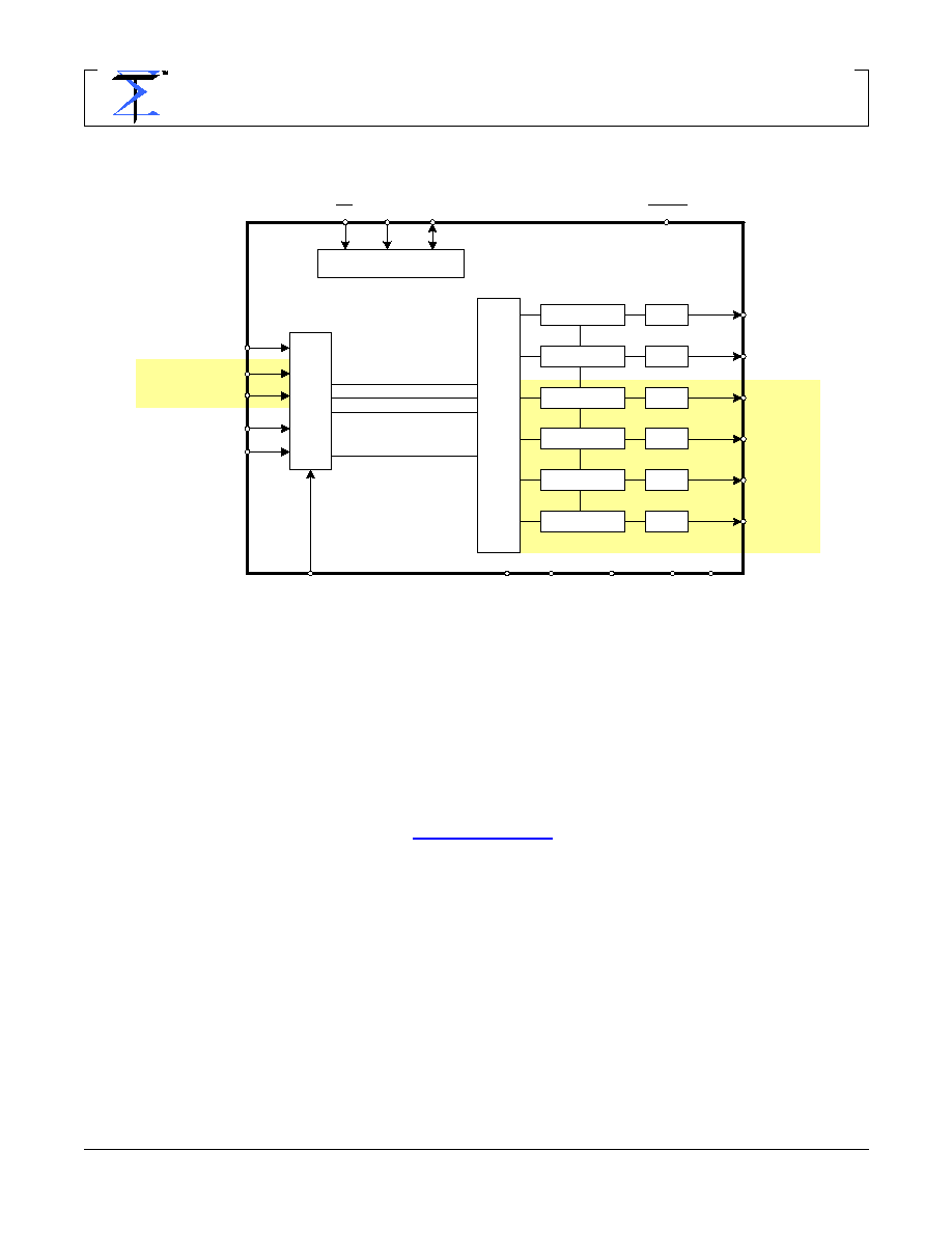
2.3.
Block Diagrams
2.4.
Related Materials
∑
Product Brief
∑
Evaluation Boards
∑
Reference Designs
2.5.
Additional Support
Additional product and company information can be obtained by going to the
SigmaTel website at:
www.sigmatel.com
I
2
C
Æ
Port
DSP
I
2
S
Port
DAC
DAC
DAC
DAC
DAC
DAC
D_LRCLK
D_SCLK
SDI3
SDI2
SDI1
SDATA
SCLK
DAC_RF
DAC_LF
DAC_LR
DAC_RR
DAC_CTR
DAC_BASS
RESET
CS
MCLK
DVdd
DVss
VREF
AVdd AVss
VOLUME
VOLUME
VOLUME
VOLUME
VOLUME
VOLUME
STAC9461 ONLY
STAC9461
ONLY
Figure 1. STAC9461 & STAC9463 Block Diagram