Preliminary Rev. 0.4 5/06
Copyright © 2006 by Silicon Laboratories
Si530/531
This information applies to a product under development. Its characteristics and specifications are subject to change without notice.
Si530/531
C
R Y S TA L
O
S C I L L A T O R
(XO)
(10 MH
Z
T O
1.4 GH
Z
)
Features
Applications
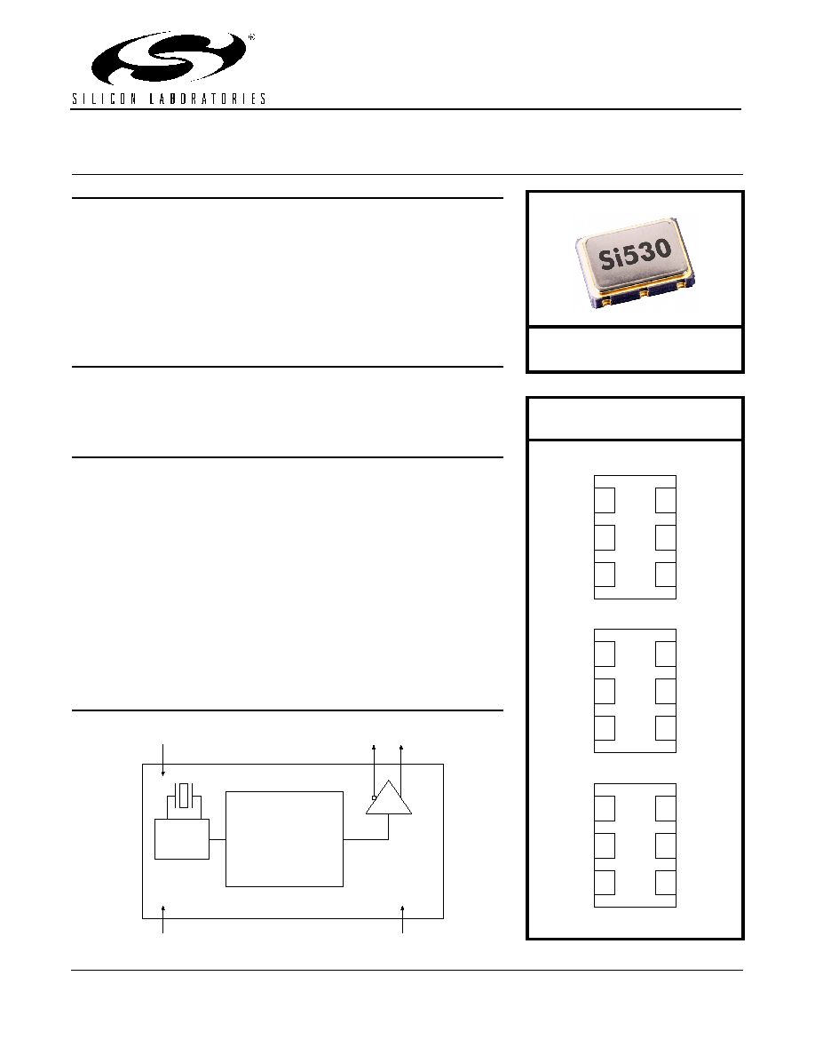
Description
The Si530/531 XO utilizes Silicon Laboratories' advanced DSPLL
Æ
circuitry
to provide a low jitter clock at high frequencies. The Si530/531 is available
with any-rate output frequency from 10 to 945 MHz and select frequencies to
1400 MHz. Unlike a traditional XO, where a different crystal is required for
each output frequency, the Si530/531 uses one fixed crystal to provide a
wide range of output frequencies. This IC based approach allows the crystal
resonator to provide exceptional frequency stability and reliability. In addition,
DSPLL clock synthesis provides superior supply noise rejection, simplifying
the task of generating low jitter clocks in noisy environments typically found in
communication systems. The Si530/531 IC based XO is factory configurable
for a wide variety of user specifications including frequency, supply voltage,
output format, and temperature stability. Specific configurations are factory
programmed at time of shipment, thereby eliminating long lead times
associated with custom oscillators.
Functional Block Diagram
Available with any-rate output
frequencies from 10 MHz to 945 MHz
and select frequencies to 1.4 GHz
3rd generation DSPLL
Æ
with superior
jitter performance
3x better frequency stability than
SAW-based oscillators
Internal fixed crystal frequency
ensures high reliability and low
aging
Available CMOS, LVPECL,
LVDS, and CML outputs
3.3, 2.5, and 1.8 V supply options
Industry-standard 5 x 7 mm
package and pinout
Pb-free/RoHS-compliant
SONET/SDH
Networking
SD/HD video
Clock and data recovery
FPGA/ASIC clock generation
Fixed
Frequency
XO
Any-rate
10≠1400 MHz
DSPLLÆ
Clock
Synthesis
V
DD
CLK+
CLK≠
OE
GND
Ordering Information:
See page 6.
Pin Assignments:
See page 5.
(Top View)
Si5602
1
2
3
6
5
4
GND
OE
V
DD
CLK+
CLK≠
NC
1
2
3
6
5
4
GND
NC
V
DD
CLK+
NC
OE
1
2
3
6
5
4
GND
NC
V
DD
CLK+
CLK≠
OE
Si530 (LVDS/LVPECL/CML)
Si530 (CMOS)
Si531 (LVDS/LVPECL/CML)
P
R E L I M I N A R Y
D
A TA
S
H E E T

Si530/531
2
Preliminary Rev. 0.4
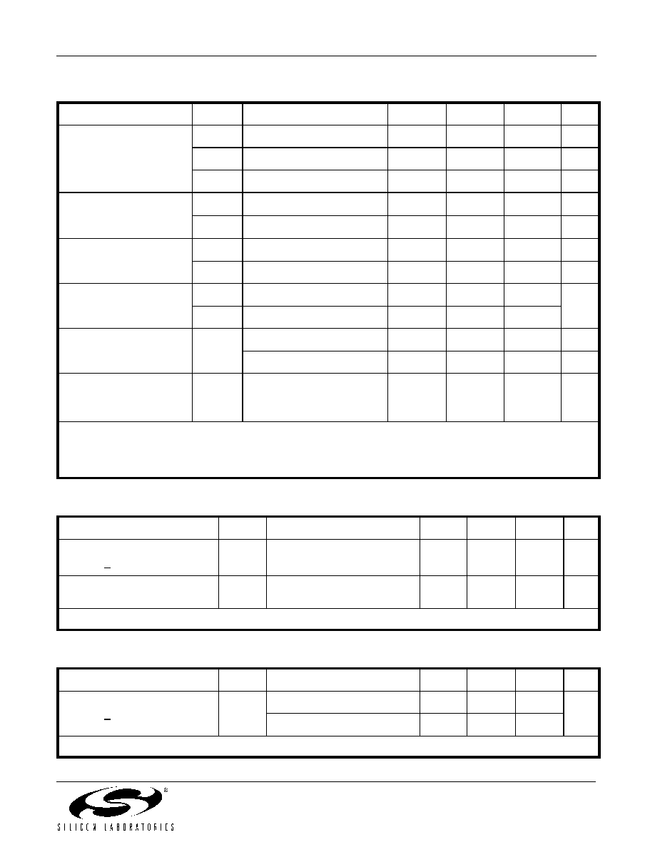
1. Electrical Specifications
Table 1. Recommended Operating Conditions
Parameter
Symbol
Test Condition
Min
Typ
Max
Units
Supply Voltage
1
V
DD
3.3 V option
2.97
3.3
3.63
V
2.5 V option
2.25
2.5
2.75
1.8 V option
1.71
1.8
1.89
Supply Current
I
DD
Output enabled
--
90
--
mA
TriState mode
--
60
--
Output Enable (OE)
2
V
IH
0.75 x V
DD
--
--
V
V
IL
--
--
0.5
Operating Temperature Range
T
A
≠40
--
85
∫C
Notes:
1. Selectable parameter specified by part number. See Section 3. "Ordering Information" on page 6 for further details.
2. OE pin includes a 17 k
pullup resistor to V
DD
. Pulling OE to ground causes outputs to tristate.
Table 2. CLK± Output Frequency Characteristics
Parameter
Symbol
Test Condition
Min
Typ
Max
Units
Nominal Frequency
1,2
f
O
LVPECL/LVDS/CML
10
--
945
MHz
CMOS
10
--
160
Initial Accuracy
f
i
Measured at +25 ∞C at
time of shipping
--
±1.5
--
ppm
Temperature Stability
1,3
f/f
O
≠20
≠50
--
--
+20
+50
ppm
Aging f
a
Frequency drift over
projected 15 year life
--
--
±10
ppm
Powerup Time
4
t
OSC
--
--
10
ms
Notes:
1. See Section 3. "Ordering Information" on page 6 for further details.
2. Specified at time of order by part number. Also available in frequencies from 970 to 1134 MHz and 1213 to 1417 MHz.
3. Selectable parameter specified by part number.
4. Time from powerup or tristate mode to f
O
.
Si530/531
Preliminary Rev. 0.4
3
Table 3. CLK± Output Levels and Symmetry
Parameter
Symbol
Test Condition
Min
Typ
Max
Units
LVPECL Output Option
1
V
O
mid-level
V
DD
≠ 1.42
--
V
DD
≠ 1.25
V
V
OD
swing (diff)
1.1
--
1.9
V
PP
V
SE
swing (single-ended)
0.5
--
0.93
V
PP
LVDS Output Option
2
V
O
mid-level
1.125
1.20
1.275
V
V
OD
swing (diff)
0.32
0.40
0.50
V
PP
CML Output Option
2
V
O
mid-level
--
V
DD
≠ 0.75
--
V
V
OD
swing (diff)
0.70
0.95
1.20
V
PP
CMOS Output Option
3
V
OH
I
OH
= 32 mA
0.8 x V
DD
--
V
DD
V
V
OL
I
OL
= 32 mA
--
--
0.4
Rise/Fall time (20/80%)
t
R,
t
F
LVPECL/LVDS/CML
--
--
350
ps
CMOS with CL = 15 pF
--
1
--
ns
Symmetry (duty cycle)
SYM
LVPECL:
V
DD
≠ 1.3 V (diff)
LVDS:
1.25 V (diff)
CMOS:
V
DD
/2
45
--
55
%
Notes:
1. 50
to V
DD
≠ 2.0 V.
2. R
term
= 100
(differential).
3. C
L
= 15 pF
Table 4. CLK± Output Phase Jitter
Parameter
Symbol
Test Condition
Min
Typ
Max
Units
Phase Jitter (RMS)*
for F
OUT
> 500 MHz
J
12 kHz to 20 MHz (OC-48)
50 kHz to 80 MHz (OC-192)
--
--
0.27
0.30
--
--
ps
Phase Jitter (RMS)*
for F
OUT
of 125 to 500 MHz
J
12 kHz to 20 MHz (OC-48)
--
0.50
--
ps
*Note: Differential Modes: LVPECL/LVDS/CML. Refer to AN256 for further information.
Table 5. CLK± Output Period Jitter
Parameter
Symbol
Test Condition
Min
Typ
Max
Units
Period Jitter*
for F
OUT
< 160 MHz
J
PER
RMS
--
1
--
ps
Peak-to-Peak
--
5
--
*Note: Any output mode, including CMOS, LVPECL, LVDS, CML. N = 1000 cycles.
Si530/531
4
Preliminary Rev. 0.4
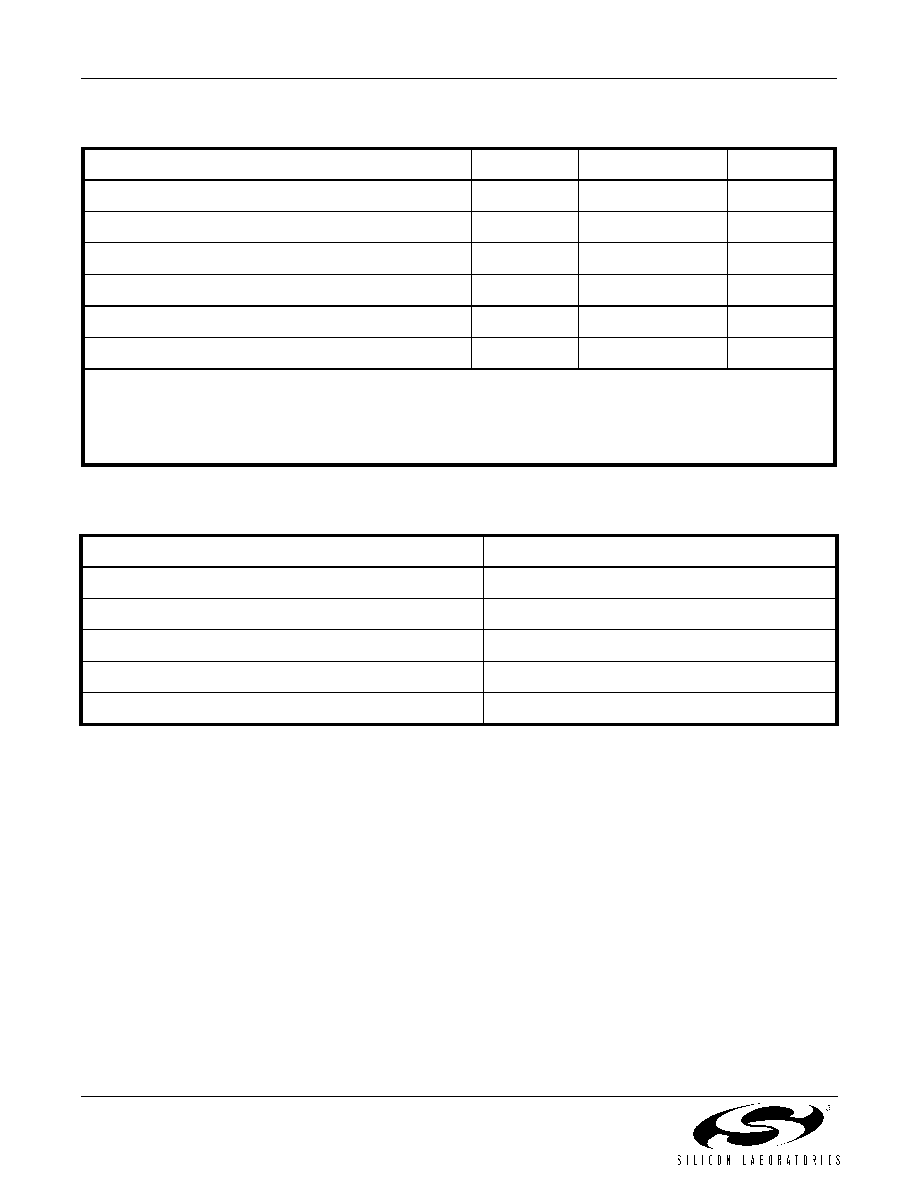
Table 6. Absolute Maximum Ratings
1
Parameter
Symbol
Rating
Units
Supply Voltage
V
DD
≠0.5 to +3.8
Volts
Input Voltage (any input pin)
V
I
≠0.5 to V
DD
+ 0.3
Volts
Storage Temperature
T
S
≠55 to +125
∫C
ESD Sensitivity (HBM, per JESD22-A114)
ESD
>2500
Volts
Soldering Temperature (Pb-free profile)
2
T
PEAK
260
∫C
Soldering Temperature Time @ T
PEAK
(Pb-free profile)
2
t
P
10
seconds
Notes:
1. Stresses beyond those listed in Absolute Maximum Ratings may cause permanent damage to the device. Functional
operation or specification compliance is not implied at these conditions.
2. Refer to Si5xx Packaging FAQ available for download at
www.silabs.com/VCXO
for further information, including
soldering profiles.
Table 7. Environmental Compliance
The Si530/531 meets the following qualification test requirements.
Parameter
Conditions/ Test Method
Mechanical Shock
MIL-STD-883F, Method 2002.3 B
Mechanical Vibration
MIL-STD-883F, Method 2007.3 A
Solderability
MIL-STD-883F, Method 203.8
Gross & Fine Leak
MIL-STD-883F, Method 1014.7
Resistance to Solvents
MIL-STD-883F, Method 2016

Si530/531
Preliminary Rev. 0.4
5
2. Pin Descriptions
Table 8. Pinout for Si530 Series
Pin
Symbol
LVDS/LVPECL/CML Function
CMOS Function
1
OE (CMOS only)
No connection
Output enable
0 = clock output disabled (outputs tristated)
1 = clock output enabled
2
OE
(LVPECL,LVDS,
CML)
Output enable
0 = clock output disabled (outputs tristated)
1 = clock output enabled
No connection
3
GND
Electrical and Case Ground
Electrical and Case Ground
4
CLK+
Oscillator Output
Oscillator Output
5
CLK≠
Complementary output
No connection
6
V
DD
Power Supply Voltage
Power Supply Voltage
Table 9. Pinout for Si531 Series
Pin
Symbol
LVDS/LVPECL/CML Function
1
OE (LVPECL, LVDS, CML)
Output enable
0 = clock output disabled (outputs tristated)
1 = clock output enabled
2
No connection
No connection
3
GND
Electrical and Case Ground
4
CLK+
Oscillator Output
5
CLK≠
Complementary output
6
V
DD
Power Supply Voltage
1
2
3
6
5
4
GND
NC
V
DD
CLK+
NC
OE
(Top View)
1
2
3
6
5
4
GND
OE
V
DD
CLK+
CLK≠
NC
1
2
3
6
5
4
GND
NC
V
DD
CLK+
CLK≠
OE
Si530
LVDS/LVPECL/CML
Si530
CMOS
Si531
LVDS/LVPECL/CML

Si530/531
6
Preliminary Rev. 0.4
3. Ordering Information
The Si530/531 XO was designed to support a variety of options including frequency, temperature stability, output
format, and V
DD
. Specific device configurations are programmed into the Si530/531 at time of shipment.
Configurations can be specified using the Part Number Configuration chart below. Silicon Laboratories provides a
web browser-based part number configuration utility to simplify this process. Refer to
www.silabs.com/VCXOPartNumber
to access this tool and for further ordering instructions. The Si530 and Si531
XO series are supplied in an industry-standard, RoHS compliant, 6-pad, 5 x 7 mm package. The 531 Series
supports an alternate OE pinout (pin #1) for the LVPECL, LVDS, and CML output formats. See Tables 8 and 9 for
the pinout differences between the Si530 and Si531 series.
Figure 1. Part Number Convention
530
X
XXXMXXX
X
1
st
Option Code
V
Output Format
A 3.3
LVPECL
B 3.3
LVDS
C 3.3 CMOS
D 3.3 CML
E 2.5
LVPECL
F 2.5
LVDS
G 2.5 CMOS
H 2.5 CML
J 1.8
CMOS
K 1.8
CML
Notes:
CMOS available to 160 MHz.
B
G
R
Frequency (e.g., 622M080 is 622.080 MHz)
Available frequency range is 10 to 945 MHz, 970 to 1134 MHz, and
1213 to 1417 MHz. The position of "M" shifts to denote higher or
lower frequencies.
Tape & Reel Packaging
Blank = Trays
Operating Temp Range (∞C)
G
-40 to +85∞C
Part Revision Letter
2
nd
Option Code
Temp Stability (ppm, max, ±)
A 50
B 20
530 XO Product
Family
Example P/N: 530AB622M080BGR is a 5 x 7 XO in a 6 pad package. The frequency is 622.080 MHz, with a 3.3 V supply and PECL output.
Temperature stability is specifed as ± 20 ppm. The part is specified for -40 to +85 ∞C ambient temperature range operation and is shipped in
tape and reel format.
DD
Si530/531
Preliminary Rev. 0.4
7
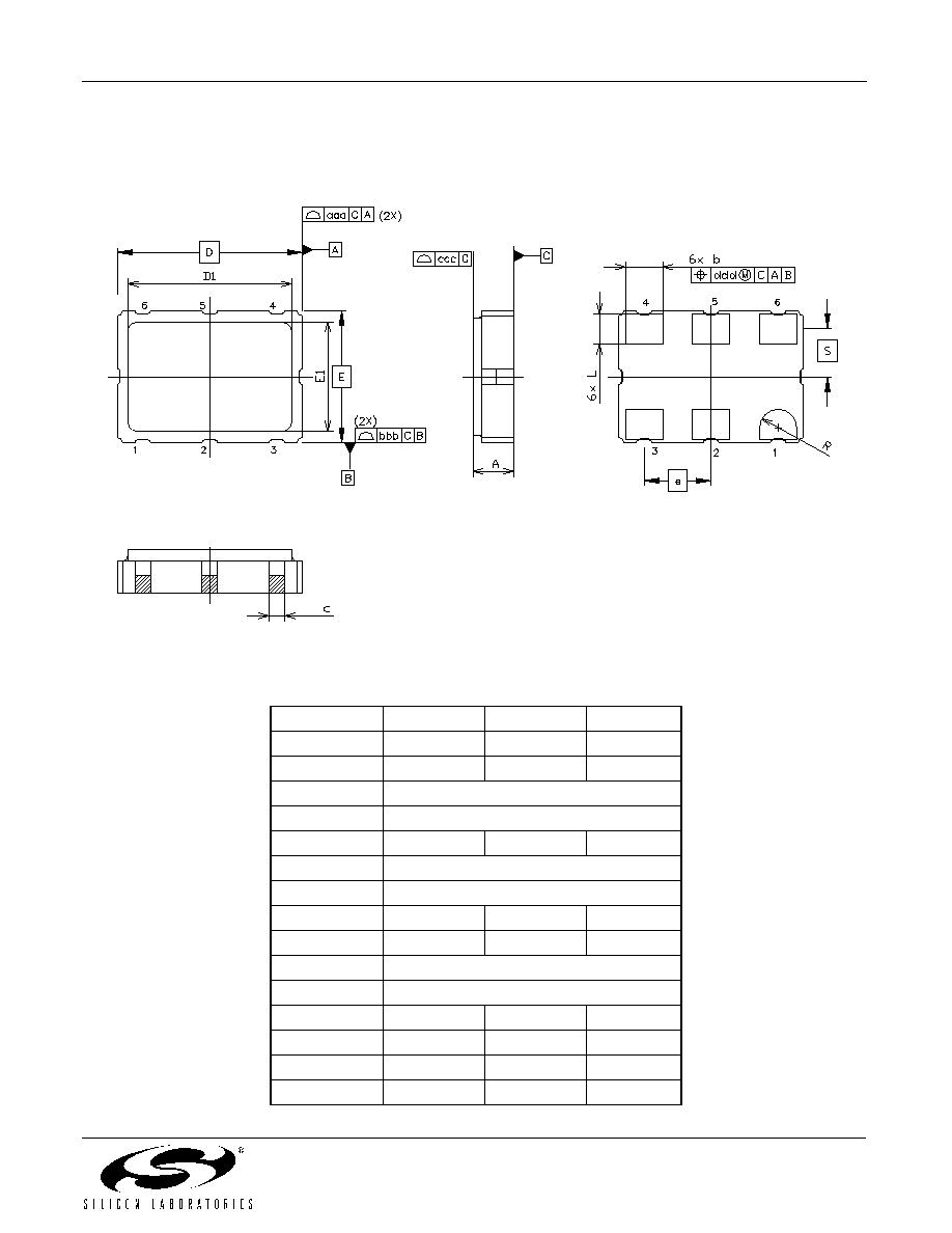
4. Outline Diagram and Suggested Pad Layout
Figure 2 illustrates the package details for the Si530/531. Table 10 lists the values for the dimensions shown in the
illustration.
Figure 2. Si530/531 Outline Diagram
Table 10. Package Diagram Dimensions (mm)
Dimension
Min
Nom
Max
A
1.45
1.65
1.85
b
1.2
1.4
1.6
c
0.60 TYP.
D
7.00 BSC.
D1
6.10
6.2
6.30
e
2.54 BSC.
E
5.00 BSC.
E1
4.30
4.40
4.50
L
1.07
1.27
1.47
S
1.815 BSC.
R
0.7 REF.
aaa
--
--
0.15
bbb
--
--
0.15
ccc
--
--
0.10
ddd
--
--
0.10

Si530/531
8
Preliminary Rev. 0.4
5. 6-Pin PCB Land Pattern
Figure 3 illustrates the 6-pin PCB land pattern for the Si530/531. Table 11 lists the values for the dimensions shown
in the illustration.
Figure 3. Si530/531 PCB Land Pattern
Table 11. PCB Land Pattern Dimensions (mm)
Dimension
Min
Max
D2
5.08 REF
e
2.54 BSC
E2
4.15 REF
GD
0.84
--
GE
2.00
--
VD
8.20 REF
VE
7.30 REF
X
1.70 TYP
Y
2.15 REF
ZD
--
6.78
ZE
--
6.30
Notes:
1. Dimensioning and tolerancing per the ANSI Y14.5M-1994 specification.
2. Land pattern design based on IPC-7351 guidelines.
3. All dimensions shown are at maximum material condition (MMC).
4. Controlling dimension is in millimeters (mm).
Si530/531
Preliminary Rev. 0.4
9
D
OCUMENT
C
HANGE
L
IST
Revision 0.3 to Revision 0.4
Updated references from Si530 to Si530/531.
Added Table 9, "Pinout for Si531 Series," on page 5.
Updated 3. "Ordering Information" on page 6 to add
the Si531 series.
Added Table 7, "Environmental Compliance," on
page 4.

Si530/531
10
Preliminary Rev. 0.4
C
ONTACT
I
NFORMATION
Silicon Laboratories Inc.
4635 Boston Lane
Austin, TX 78735
Tel: 1+(512) 416-8500
Fax: 1+(512) 416-9669
Toll Free: 1+(877) 444-3032
Email: VCXOinfo@silabs.com
Internet: www.silabs.com
Silicon Laboratories, Silicon Labs, and DSPLL are trademarks of Silicon Laboratories Inc.
Other products or brandnames mentioned herein are trademarks or registered trademarks of their respective holders.
The information in this document is believed to be accurate in all respects at the time of publication but is subject to change without notice.
Silicon Laboratories assumes no responsibility for errors and omissions, and disclaims responsibility for any consequences resulting from
the use of information included herein. Additionally, Silicon Laboratories assumes no responsibility for the functioning of undescribed features
or parameters. Silicon Laboratories reserves the right to make changes without further notice. Silicon Laboratories makes no warranty, rep-
resentation or guarantee regarding the suitability of its products for any particular purpose, nor does Silicon Laboratories assume any liability
arising out of the application or use of any product or circuit, and specifically disclaims any and all liability, including without limitation conse-
quential or incidental damages. Silicon Laboratories products are not designed, intended, or authorized for use in applications intended to
support or sustain life, or for any other application in which the failure of the Silicon Laboratories product could create a situation where per-
sonal injury or death may occur. Should Buyer purchase or use Silicon Laboratories products for any such unintended or unauthorized ap-
plication, Buyer shall indemnify and hold Silicon Laboratories harmless against all claims and damages.