Silan
Semiconductors
SC50560
HANGZHOU SILAN MICROELECTRONICS JOINT-STOCK CO.,LTD
Rev: 2.3
2002-03-21
1
INFRARED REMOTE CONTROL
TRANSMITTER
DESCRIPTION
The
SC50560 is a remote control transmitter utilizing CMOS
technology housed in a 20-pin DIP or SO package. A 4x8 key matrix
and extension bit inputs allow the transmission of up to 256
instructions. The transmission code consists of 16 bits code (8 bits
custom code and 8 bits data code) and a leader code.
Pin assignments and application circuit of SC50560 are optimized
for easy PCB layout and cost saving advantage for remote control
applications.
FEATURES
* CMOS technology
* Low power consumption
* Least external components
* LED power dissipation is less during the transmission of
instructions
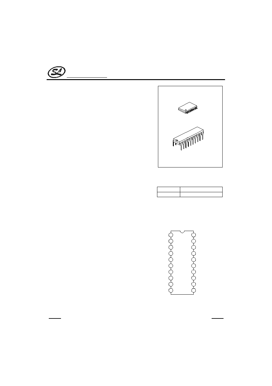
DIP-20
SOP-20
ORDERING INFORMATION
SC50560
SC50560S
DIP-20 Package
SOP-20 Package
APPLICATIONS
PIN CONFIGURATION
* Audio Equipment
* Television
* Video Cassette Recorder
* Air Condition
15
16
14
11
13
2
1
3
5
4
6
7
8
9
10
12
19
20
18
17
Vss
TEST
SEL
OSCI
OSCO
CS
KIO0
KO7
KO6
KO5
KO4
KO3
KO2
KO1
KO0
D
OUT
V
DD
KIO1
KIO2
KIO3
SC50560
Silan
Semiconductors
SC50560
HANGZHOU SILAN MICROELECTRONICS JOINT-STOCK CO.,LTD
Rev: 2.3
2002-03-21
2
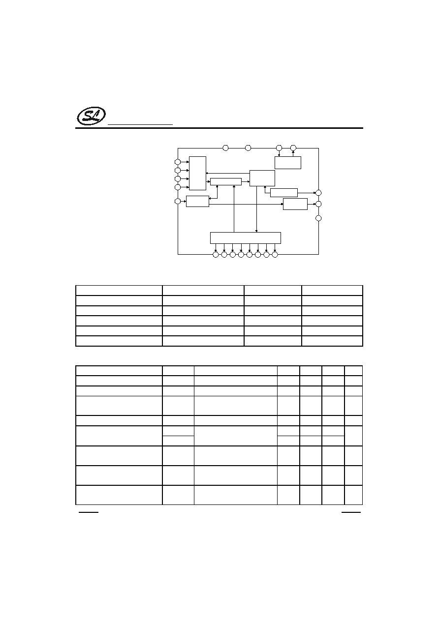
BLOCK
DIAGRAM
Scan
Key
Input
Scan Signal Generating Circuit
Output
Controller
Timing
Generator
Oscillation
Circuit
9
7
8
10
16
18
17
15
14
13
12
11
19
2
5
4
1
20
KIO0
KIO1
KIO2
KIO3
S1 S2 S3 S4 S5 S6 S7 S8
VSS
VDD
6
Code
Transfer
CS
Data Encoder
Test Circuit
3
OSCO
OSCI
TEST
DOUT
SEL
ABSOLUTE MAXIMUM RATINGS
(Tamb=25
�
C)
Characteristic Symbol Value
Unit
Supply Voltage
V
CC
-0.3 ~ 5.5
V
Input Voltage
V
IN
Vss-0.3V ~ V
DD
+0.3V
V
Output Voltage
V
OUT
Vss
Vo
V
DD
V
Operating Temperature
Topr
-20 ~ 70
�
C
Storage Temperature
Tstg
-40 ~ +125
�
C
ELECTRICAL CHARACTERISTICS
(Tamb=25
�
C, V
DD
=3.0V,Vss=0,Unless otherwise specified)
Parameter Symbol
Test
Conditions
Min
Typ
Max
Unit
Supply Voltage
V
DD
Fosc =455KHz
2.0
3.0
4.0
V
Operating Current
I
OP
Fosc =455KHz
0.12
0.3
mA
Stand-by Current
I
SB
OSCO =V
DD
KIO0~KIO3= V
DD
TEST = Vss SEL = Vss
0.1
1
�
A
High level Output Current (Dout)
I
OH
V
OH
=2V
-1.0
-13
mA
I
OL
0.5
1.2
Low Level Output Current
(Dout, KO0~KO7)
I
KO0~KO7
V
OL
=0.9V
4.5
5.3
mA
High Level Input Voltage (CS)
(KIO0~KIO3)
V
IH
V
DD
=3.0V
0.7 V
DD
V
DD
V
Low Level Input Voltage (CS)
(KIO0~KIO3)
V
IL
V
DD
=3.0V
0
0.3V
DD
V
Input Pull-High Resistance
(KIO0~KIO3)
R
IN
V
DD
=3.0V
55
70
85
k
Silan
Semiconductors
SC50560
HANGZHOU SILAN MICROELECTRONICS JOINT-STOCK CO.,LTD
Rev: 2.3
2002-03-21
3
PIN DESCRIPTION
Pin No.
Pin Name
Input/output
Description
1
V
SS
--
Negative Power Supply
2
TEST
I
Test Pin. This pin is normally connected to VSS.
3
SEL
I
Select Pin for SC50560-001/003.
4
OSCI
I
Oscillation Input Pin
5
OSCO
O
Oscillation Output Pin
6
CS
I
Code Select Pin
7~10
KIO0~KIO3
I/O
Input/Output Pins
18~11
KO0~KO7
O
Scan Output Pins
19
Dout
O
Output Pin
20
V
DD
--
Positive Power Supply
FUNCTIONAL DESCRIPTION
SC50560 is capable of transmitting up to 256 different instructions and 8 bits custom codes using a 16-bit PCM
Code with a leader code. Furthermore, oscillation is normally stopped when there is no operating, thereby, lower
power dissipation.
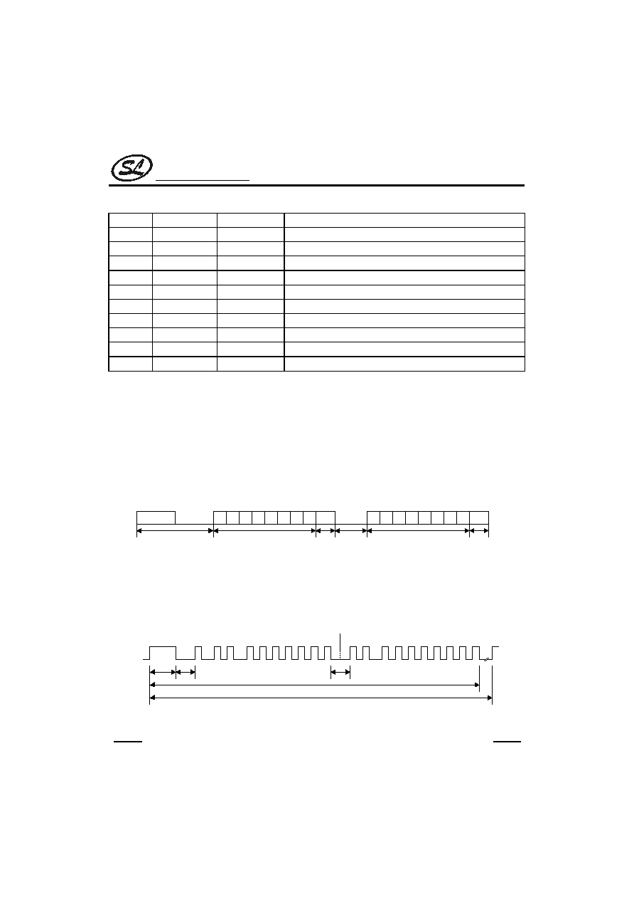
1. TRANSMISSION CODE
SC50560 transmission code consists of a leader code, 8 bits custom code (C0 to C7) followed by a sync. bit
and 8 bits data code (D0 to D7) followed another sync. bit. The custom and the data codes are separated by a
separator. Please refer to the diagram below:
C1 C2 C3
C5
C4
C6
Leader Pulse
8 Bits Custom Code
C7
SYNC
D0 D1 D2 D3 D4 D5 D6 D7
SYNC
Sync. Bit
8 Bits Data Code
Sync. Bit
Seperator
Figure 1. SC50560 Transmission Code Format
One transmission Code Word consists of a 19-bit pulse (that is the leader pulse plus the 16 bits code) and the
separator. It is transferred in a 63.4ms for as long as the key is depressed. Please refer to the diagram below:
C0
SEPARATOR
8.4ms
4.2ms
ONE CODE WORD
63.4ms
4.2ms
8BITS CUSTOM CODE
LEADER CODE
8BITS DATA CODE
C1 C2
C3 C4 C5 C6 C7
SYNC
D0 D1
D2 D3 D4 D5 D6 D7
SYNC
Figure 2. SC50560 Detailed Code Word Format

Silan
Semiconductors
SC50560
HANGZHOU SILAN MICROELECTRONICS JOINT-STOCK CO.,LTD
Rev: 2.3
2002-03-21
4
LEADER CODE
The leader code is located at the beginning of the transmission code and is made up of 8.4ms HIGH & 4.2ms
LOW pulse and is modulated in 38KHz providing easy identification of the reception code head bit at the receiver.
CUSTOM CODE
Custom Code may be selected by connection CS Input with Scan Output (KO0 to KO4). An example of a
custom code selection is shown in the diagram below.
6
18
17
16
15
14
CS
KO0
KO1
KO2
KO4
KO3
Custom Code
C0
1
C1
0
C2
1
C3
0
C4
1
C5
0
C6
0
C7
0
Figure 3. custom Code Selection Example
DATA CODE
D0 to D7 of the transmission code are the data code bits. When CS Input and the Scan Output (KO5 to
KO7) are connected, data bits--D5 to D7 becomes the system extended code bits. An example of the
Extended code Bits Selection is given in the diagram below:
Data Code
D5
D6
D7
SW = OFF
1
0
0
SW = ON
1
0
1
6
CS
18
KO5
17
KO6
16
KO7
Figure 4. Extended Code Selection
2. SEPARATOR
The separator demarcates the custom code and the data code. It consists of a 4.2ms LOW pulse interval and
can be determined at the receiver so theat any interference with other remote control system may be avoided.
Please refer to Figure 2.

Silan
Semiconductors
SC50560
HANGZHOU SILAN MICROELECTRONICS JOINT-STOCK CO.,LTD
Rev: 2.3
2002-03-21
5
3. CARRIER
The carrier of the transmission signal is 38KHz and one pulse width is 0.52ms. Therefor, with the exception of
the leader code, there are twenty 38KHz clock in one pulse width. Please refer to the diagram below.
0.52ms
8.7
�s
26.3
�s
Figure 5. Transmission Signal Carrier Diagram
4. KEY INPUT
By connecting the input pins � KI0 to KI3 and scan output pins �KO0 to KO7 (also known as the Standard Keys),
a 4x8 key matrix may be formed. Likewise, a maximum of 256 instructions may be provided by connecting the input
CS with the scan output �KO0 to KO7 (also known as the Extended Keys). When two or more standard keys are
pressed, the transmission output Dout is kept at LOW and no transmission code is outputted. Please refer to the
tables below.
Data
Key Input
D0 D1
KI0
0
0
KI1
1
0
KI2
0
1
KI3
1
1
Data Data
Scan Output
D2 D3 D4
CS Input
D5 D6 D7
KO0
0
0
0
KO5
1
--
--
KO1
1
0
0
KO6
--
1
--
KO2
0
1
0
KO7
--
--
1
KO3
1
1
0
KO4
0
0
1
KO5
1
0
1
KO6
0
1
1
KO7
1
1
1