5200 St. Patrick St., Montreal
The Old Railway, Princes Street
Que., H4E 4N9, Canada
Ulverston, Cumbria, LA12 7NQ, UK
Tel: 514-768-8000
Tel: 01 229 581 551
Fax: 514-768-8889
Fax: 01 229 581 554
QF-84
NSL-32SR3
Optocoupler
Features
∑
Compact, moisture resistant package
∑
Low "on" resistance
∑
Low LED current
∑
Fast rise and decay time
∑
Passive resistance output
∑
Best distortion characteristics
Description
This optocoupler consists of an LED input optically
coupled to a photocell. The photocell resistance is
high when the LED current is "off" and low resistance
when the LED current is "on".
Absolute Maximum Ratings
Storage Temperature
-40 to +75
∞
C
Operating Temperature
-40 to +75
∞
C
Soldering Temperature (1)
260
∞
C
Isolation Voltage (peak)
2000V
+
-
LED
Photocell
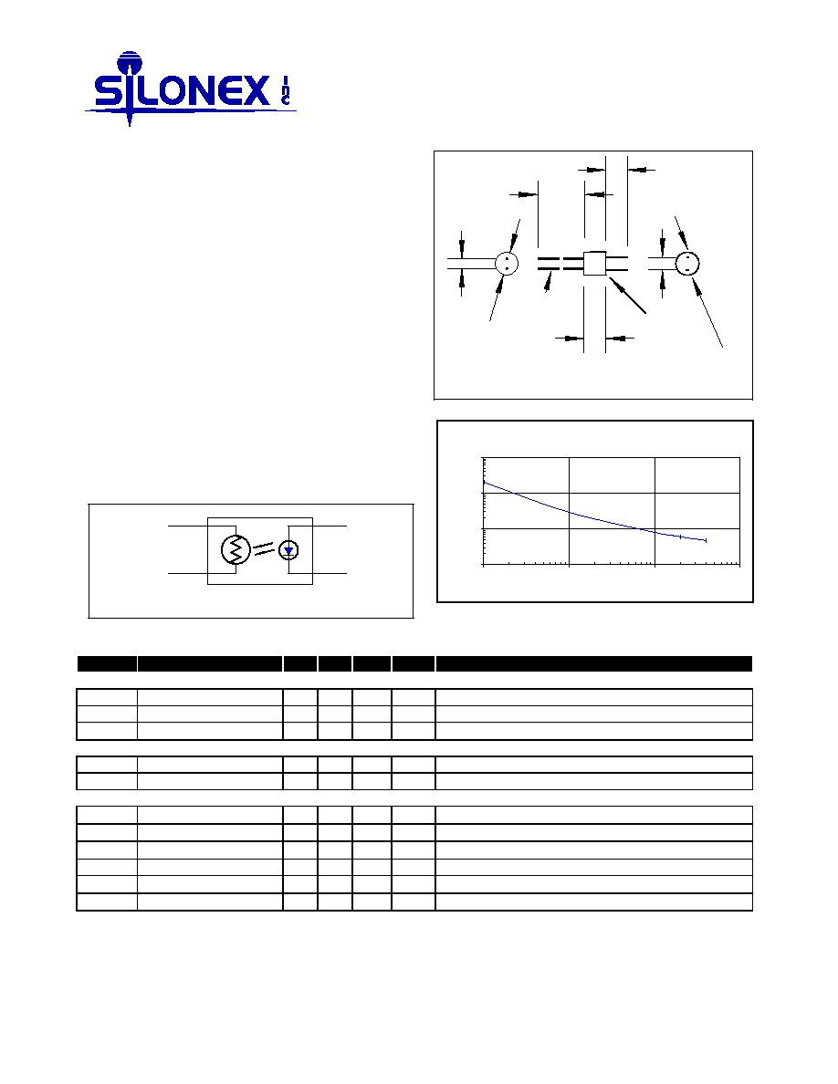
Circuit Schematic
Photocell
LED
Color dot
0.45-0.56
cell leads
Dimensions in mm.
Lead spacing tolerance: +/-0.13
Anode lead
0.25 x 0.51
Cathode lead
0.25 x 0.64
6.0 - 6.5
+
-
25.4 min.
5.7 min.
2.54
5.72 - 6.22
3.30
Photocell Resistance vs. LED Current
10
100
1000
10000
0.1
1
10
100
Current (mA)
Resistance (
)
Electrical Characteristics
(T
A
=25
∞
C)
Symbol Parameter
Min. Typ. Max. Units Test Conditions
LED
I
F
Forward Current
25
mA
V
F
Forward Voltage
2.5
V
I
F
= 20 mA
I
R
Reverse Current
10
µ
A V
R
= 4V
Cell
V
C
Maximum Cell Voltage
60
V
(Peak AC or DC)
P
D
Power Dissipation
50
mW (2)
Coupled
R
ON
On Resistance
60
I
F
= 20 mA
150
I
F
= 5 mA
R
OFF
Off Resistance
25
M
10 sec after I
F
= 0, 5Vdc on cell.
T
R
Rise Time
5
msec Time to 63% of final conductance @ I
F
= 5mA
T
F
Decay Time
10
msec Time to 100K
after removal of I
F
= 5mA
Cell Temp Coefficient
0.7
%/
∞
C I
F
> 5 mA
Specifications subject to change without notice
104058 REV 3
Note: (1) >2 mm from case for <5 sec.
(2) Derate linearly to 0 at 75
∞
C
