 | –≠–ª–µ–∫—Ç—Ä–æ–Ω–Ω—ã–π –∫–æ–º–ø–æ–Ω–µ–Ω—Ç: SP4415CN | –°–∫–∞—á–∞—Ç—å:  PDF PDF  ZIP ZIP |
SP4415DS/06
SP4415 Electroluminescent Lamp Driver
© Copyright 1996 Sipex Corporation
1
s
2.2 V- 3.6 V Battery Operation
s
50 nA Maximum Standby Current
s
Four Level Selectable Output
s
High Voltage Output 140V
PP
Typical
s
High Impedance Clock Signal
Conditioner
APPLICATIONS
s
Watches
s
Pagers
s
Backlit LCD Displays
SP4415
DESCRIPTION
The SP4415 is a single chip DC-AC converter ideally suited for driving electroluminescent
panels to four intensity levels. The SP4415 is capable of converting DC input voltages as low
as 2.2V into any of four AC voltage levels which can be set via external switch. A high
impedance clock input and signal conditioner allows users to connect crystal oscillators
directly to the CLK input without interfering with existing system timing, no buffering of the
crystal oscillator is necessary. The SP4415 requires only one external inductor and is offered
in an 8-pin NSOIC package. For delivery in die form, please consult the factory.
SP4415 Block Diagram
SIGNAL PROCESSING EXCELLENCE
Electroluminescent Lamp Driver
with Selectable Level Outputs
No Connect
V
DD
Level Select
V
SS
COIL
EL2
EL1
SP4415
8
7
4
3
2
1
5
6
CLK
SP4415DS/06
SP4415 Electroluminescent Lamp Driver
© Copyright 1996 Sipex Corporation
2
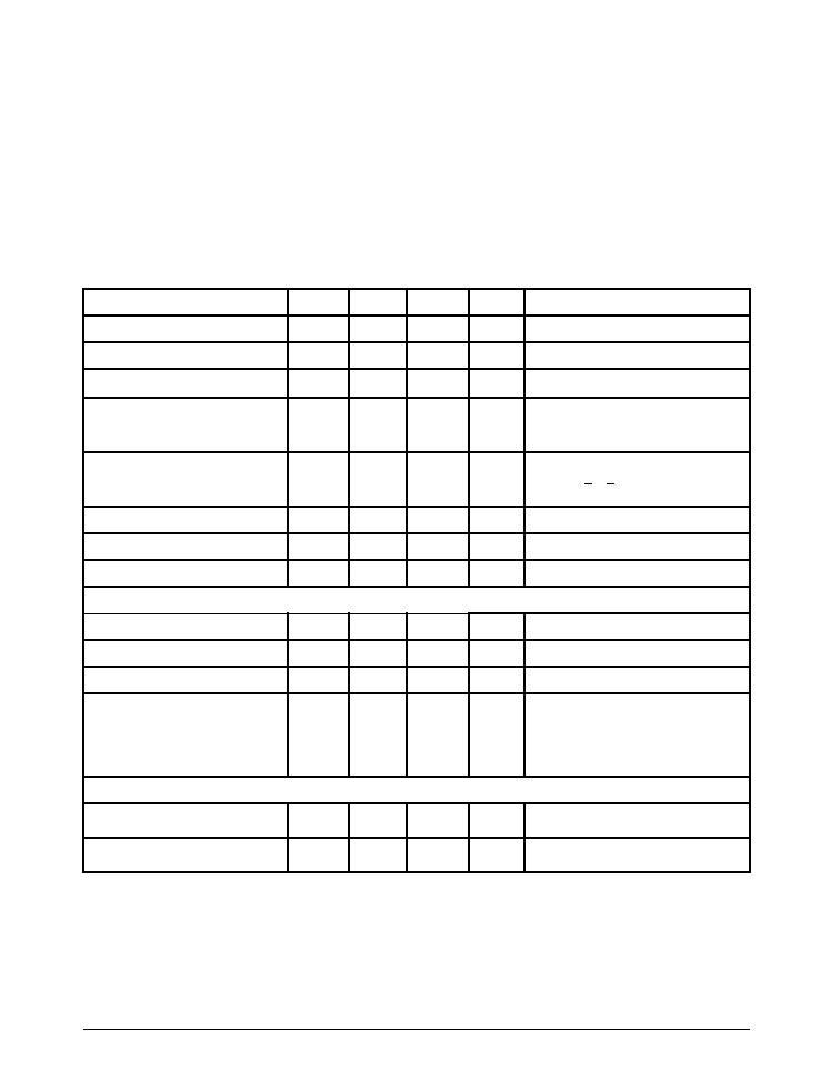
SPECIFICATIONS
T= 25
∞
C; V
DD
= 3.0V; Lamp Capacitance = 2000pF; Coil = 30 mH at 125 Ohms; Osc = 32,768Hz (Unless otherwise noted)
ABSOLUTE MAXIMUM RATINGS
These are stress ratings only and functional operation of the device at
these ratings or any other above those indicated in the operation sections
of the specifications below is not implied. Exposure to absolute maximum
rating conditions for extended periods of time may affect reliability.
V
DD
...................................................................................................7.0 V
Input Voltages/Currents
Level Select (pin 1).......................................-0.5V to (V
DD
+0.5V)
EN (pin3)............................................................................60mA
Lamp Outputs...............................................................................250V
PP
Storage Temperature....................................................-65∞C to +150∞C
Power Dissipation Per Package
8-pin NSOIC (derate 6.14mW
o
C above +70
o
C)...................................500mW
R
E
T
E
M
A
R
A
P
.
N
I
M
.
P
Y
T
.
X
A
M
S
T
I
N
U
S
N
O
I
T
I
D
N
O
C
V
,
e
g
a
t
l
o
V
y
l
p
p
u
S
D
D
2
.
2
0
.
3
6
.
3
V
,
t
n
e
r
r
u
C
y
l
p
p
u
S
I
L
I
O
C
I
+
D
D
5
0
2
A
m
V
S
L
1
l
e
v
e
L
t
a
V
,
e
g
a
t
l
o
V
li
o
C
L
I
O
C
V
D
D
6
.
3
V
V
,
e
g
a
t
l
o
V
t
u
p
n
I
t
c
e
l
e
S
l
e
v
e
L
S
L
f
f
o
L
E
:
W
O
L
n
o
L
E
:
H
G
I
H
5
2
.
0
-
V
D
D
5
2
.
0
-
0
V
D
D
V
5
2
.
0
V
D
D
5
2
.
0
+
V
I
,
t
n
e
r
r
u
C
t
c
e
l
e
S
l
e
v
e
L
S
L
f
f
o
L
E
n
o
L
E
1
0
1
0
1
0
4
µ
A
V
D
D
0
,
V
3
=
<V
S
L
<
V
5
.
1
V
D
D
V
,
V
3
=
S
L
V
3
=
I
,
t
n
e
r
r
u
C
n
w
o
d
t
u
h
S
D
S
I
=
L
I
O
C
I
+
D
D
0
5
A
n
V
S
L
1
l
e
v
e
L
t
a
y
c
n
e
u
q
e
r
F
k
c
o
l
C
l
a
n
r
e
t
x
E
8
6
7
2
3
z
H
y
t
i
v
i
t
i
s
n
e
S
t
u
p
n
I
5
2
1
V
m
P
E
V
I
R
D
R
O
T
C
U
D
N
I
f
,
y
c
n
e
u
q
e
r
F
li
o
C
L
I
O
C
f
=
P
M
A
L
2
3
x
2
9
1
8
z
H
e
l
c
y
C
y
t
u
D
li
o
C
5
7
%
I
,
t
n
e
r
r
u
C
li
o
C
k
a
e
P
L
I
O
C
-
K
P
0
6
A
m
.
n
g
i
s
e
d
y
b
d
e
e
t
n
a
r
a
u
G
s
e
s
l
u
P
li
o
C
1
l
e
v
e
L
2
l
e
v
e
L
3
l
e
v
e
L
4
l
e
v
e
L
7
9
2
1
6
1
s
e
s
l
u
p
o
t
r
e
f
e
R
l
o
r
t
n
o
C
t
c
e
l
e
S
l
e
v
e
L
5
1
4
4
P
S
.
s
m
a
r
g
a
i
d
T
U
P
T
U
O
P
M
A
L
L
E
f
,
y
c
n
e
u
q
e
r
F
p
m
a
L
L
E
P
M
A
L
6
5
2
z
H
e
g
a
t
l
o
V
t
u
p
t
u
O
k
a
e
P
o
t
k
a
e
P
0
3
1
0
4
1
0
6
1
V
P
P
V
S
L
4
l
e
v
e
L
t
a
The information furnished herein by Sipex has been carefully reviewed
for accuracy and reliability. Its application or use, however, is solely the
responsibility of the user. No responsibility for the use of this information
is assumed by Sipex, and this information shall not explicitly or implicitly
become part of the terms and conditions of any subsequent sales
agreement with Sipex. Specifications are subject to change without
prior notice. By the sale or transfer of this information, Sipex assumes
no responsibility for any infringement of patents or other rights of third
parties which may result from its use. No license or other proprietary
rights are granted by implication or otherwise under any patent or
patent rights of Sipex Corporation.
SP4415DS/06
SP4415 Electroluminescent Lamp Driver
© Copyright 1996 Sipex Corporation
3
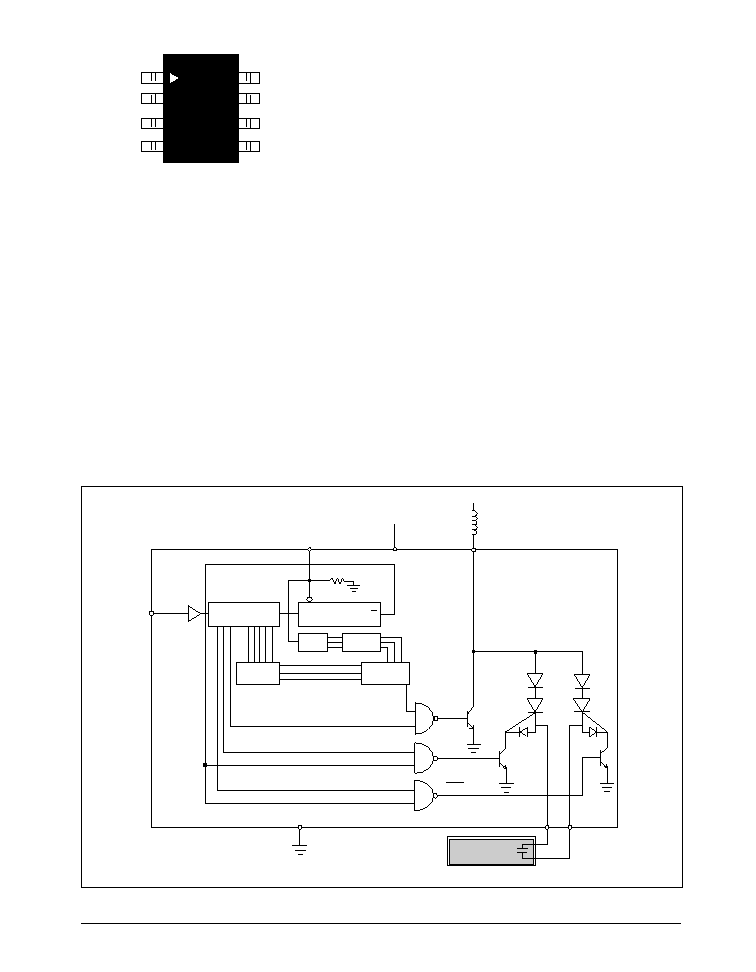
THEORY OF OPERATION
The SP4415 is made up of three basic circuit
elements, a clock signal conditioner, a divider
chain, and a switched H-bridge network. The clock
signal conditioner circuit allows users to directly
connect a crystal oscillator output to the SP4415;
no buffering is necessary. The clock input features
high impedance (50 M
), low capacitance (2.5pF)
and 200mV sensitivity. The external clock should
range from (V
DD
-1V) to ground. The SP4415 is
optimized for 32,768Hz clock signals and is allowed
to vary from 20 kHz to 60kHz.
The externally supplied clock signal provides the
circuit with a clock source used to control the
charge and discharge phases for the coil and lamp.
The suggested oscillator frequency is 32,768Hz .
This clock frequency is internally divided to create
two internal control signals, f
COIL
and f
LAMP
. For
example a 32,768Hz signal will be divided to
provide an 8,192Hz 75% duty cycle output to drive
the coil and a 256Hz 50% duty cycle output to
drive the lamp. Although the oscillator frequency
can be varied to optimize the lamp output, the ratio
of f
COIL
to f
LAMP
will always equal 32.
PIN DESCRIPTION
Pin 1 ≠ NC - Float this pin..
Pin 2 ≠ V
SS
- Ground connection
Pin 3 ≠ Coil - Coil input, connect coil from V
DD
to Pin 5.
Pin 4 ≠ Lamp2- EL voltage output, connect
directly to EL lamp.
Pin 5 ≠ Lamp1- EL voltage output, connect
directly to EL lamp.
Pin 6 ≠ V
DD
- Power supply for driver, connect to
system V
DD
.
Pin 7 ≠ Level Select - Selects the number of
inductor drive pulses.
Pin 8 ≠ Clk - Clock input for charge and
discharge cycles.
SP4415 Schematic
CLK
V
BATTERY
SCR1
SCR2
f
COIL
EL Lamp
Coil
2
3
EL1
EL2
4
8
V
ss
Level Select
V
DD
5
7
PULSE COUNT
DECODER
HON LEVEL
DECODER
PULSE COUNT
SELECTOR
2 BIT
COUNTER
9 BIT COUNTER
Q
6
7 BIT COUNTER
CLR
Q
35mH/125 ohms
f
LAMP
f
LAMP
1
2
3
4
8
7
6
5
SP4415
SP4415DS/06
SP4415 Electroluminescent Lamp Driver
© Copyright 1996 Sipex Corporation
4
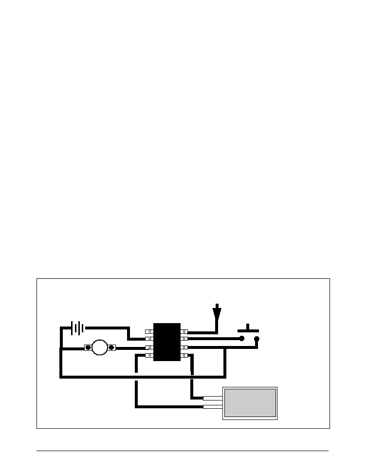
Typical SP4415CN Application Circuit
1
V
SS
Coil
Lamp
V
DD
Lamp
Level
Select
CLK
32-64KHz
From crystal oscillator
Pushbutton level select
EL Lamp
3 VDC
Coil
35mH/125
coil
NC
The EL outputs can be enabled by driving the
Level Select pin (pin 7) high.
Four intensity levels can be set via the Level
Select pin (pin 7). The intensity levels correspond
with the number of coil pulses per bridge half
cycle. The full output is represented by 16 coil
pulses, levels 3, 2, 1 have 12, 9, and 7 coil pulses.
The coil pulses transfer energy to the EL lamp;
the more pulses per cycle, the brighter the lamp.
In order to set a level, the Level Select pin should
be driven high, then driven low (or released) and
within the next one second, the Level Select pin
should be again driven high; this sequence will
increment the level selection until the highest
level (level 4) is reached. The next sequence will
force the output back to the lowest intensity level,
level 1. The Level Select pin is equipped with a
debounce circuit such that momentary (
15 mS)
opens of the input will not result in changes to the
output level.
The coil is an external component connected from
V
BATTERY
to pin 3 of the SP4415. Energy is
developed in the coil according to the equation
E
L
=1/2LI
2
where the current I is defined as
I=(V
BATTERY
-IR-V
OL
)/R
T
. In order to maximize the
energy produced by the coil, V
BATTERY
should
represent the largest voltage in the system (up to a
maximum of 6.0 v ); V
BATTERY
= 3.0 VDC with a
35mH/125
coil is a typical example. It is not
necessary that V
DD
=V
BATTERY
. The majority of the
supply current is dissipated in the coil (10mA
typical). The SP4415 itself requires less than 1mA
(700
µ
A typical). Coils are also a function of the
core material and winding used -- performance
variances may be noticeable from different coil
suppliers even though the values are the same. The
Sipex SP4415 is final tested using a 35mH/135
ohm coil. For suggested coil sources see page 8.
The f
COIL
signal controls a switch that connects the
end of the coil at pin 3 to ground or to open circuit.
The f
COIL
signal is a 75% duty cycle square wave,
switching at 1/4 the oscillator frequency. For a
32,768 Hz oscillator f
COIL
is 8,192Hz. During the
time when the f
COIL
signal is high, the coil is
connected from V
BATTERY
to ground and a charged
magnetic field is created in the coil. During the low
part of f
COIL
, the ground connection is switched
open, the field collapses and the energy in the
inductor is forced to flow toward the high voltage
H-bridge switches. f
COIL
will send 16 of these charge
pulses to the lamp; each pulse increases the voltage
drop across the lamp in discrete steps. As the
voltage potential approaches its maximum, the
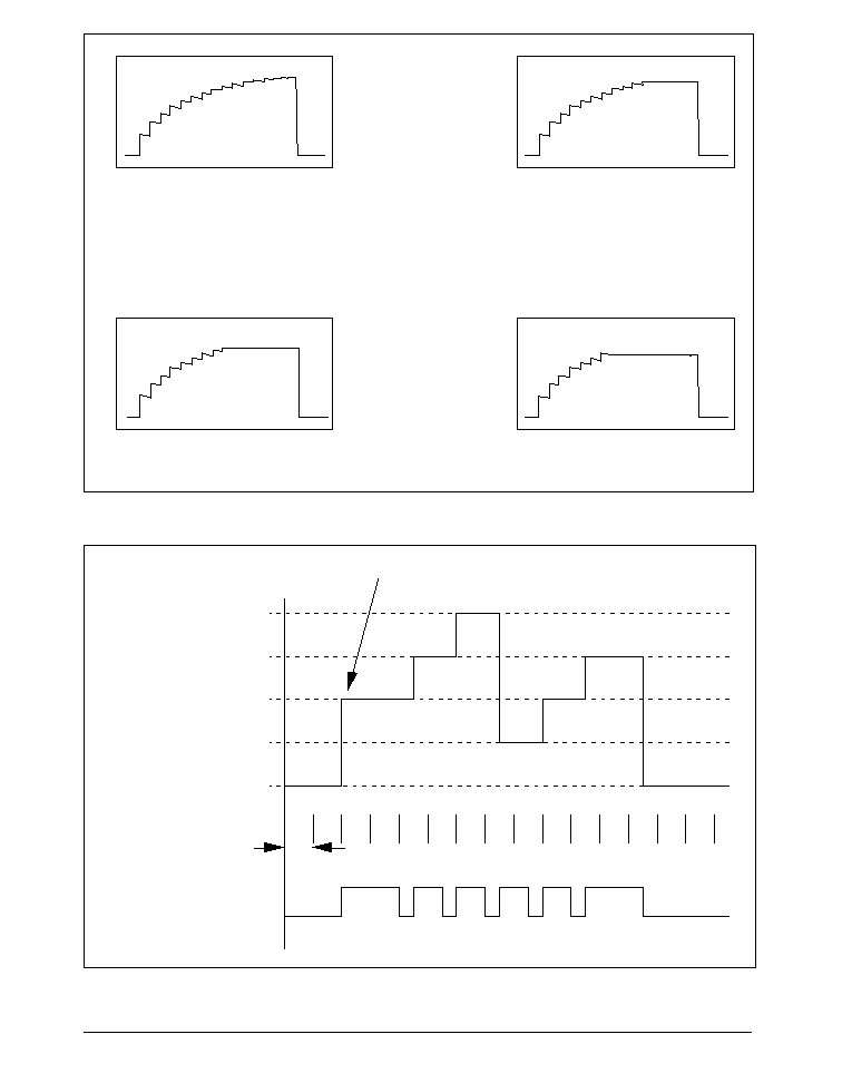
steps become shorter (see figure 1 on page 7).

SP4415DS/06
SP4415 Electroluminescent Lamp Driver
© Copyright 1996 Sipex Corporation
5
The H-bridge consists of two SCR structures that
act as high voltage switches. These two switches
control the polarity of how the lamp is charged. The
SCR switches are controlled by the f
LAMP
signal
which is the oscillator frequency divided by 128.
For a 32,768 Hz oscillator, f
LAMP
=256 Hz.
When the energy from the coil is released, a high
voltage spike is created triggering the SCR switches.
The direction of current flow is determined by
which SCR is enabled. One full cycle of the
H-bridge will create 16 voltage steps from ground
to 80V (typical) on pins 6 and 7 which are 180
degrees out of phase with each other (see figure 3
on page 7). A differential view of the outputs is
shown in figure 4 on page 7.
ELECTROLUMINESCENT TECHNOLOGY
An EL lamp is basically a strip of plastic that is
coated with a phosphorous material which emits
light (fluoresces) when a high voltage (>40V) which
was first applied across it, is removed or reversed.
Long periods of DC voltages applied to the material
tend to breakdown the material and reduce its
lifetime. With these considerations in mind, the
ideal signal to drive an EL lamp is a high voltage
sine wave. Traditional approaches to achieving this
type of waveform included discrete circuits
incorporating a transformer, transistors, and several
resistors and capacitors. This approach is large and
bulky, and cannot be implemented in most hand
held equipment. Sipex now offers low power single
chip driver circuits specifically designed to drive
small to medium sized electroluminescent panels.
All that is required is one external inductor.
Electroluminescent backlighting is ideal when used
with LCD displays, keypads, or other backlit
readouts. Its main use is to illuminate displays in
dim to dark conditions for momentary periods of
time. EL lamps typically consume less current than
LEDs or incandescent bulbs making them ideal for
battery powered products. Also, EL lamps are able
to evenly light an area without creating "hot spots"
in the display.
The amount of light emitted is a function of the
voltage applied to the lamp, the frequency at which
it is applied, the lamp material used and its size, and
lastly, the inductor used. There are many variables
which can be optimized for specific applications.
SP4415DS/06
SP4415 Electroluminescent Lamp Driver
© Copyright 1996 Sipex Corporation
6
Level 4, 16 Coil pulses
100% of V
OUT
Level 3, 12 Coil pulses
85% of V
OUT
Level 2, 9 Coil pulses
80% of V
OUT
Level 1, 7 Coil pulses
75% of V
OUT
SP4415 Level Select Control
Full
Level 4
Level 3
Level 2
Level1
OFF
Enabled
Disabled
1 sec
Previously set level
Output Intensity
Level Select
SP4415DS/06
SP4415 Electroluminescent Lamp Driver
© Copyright 1996 Sipex Corporation
7
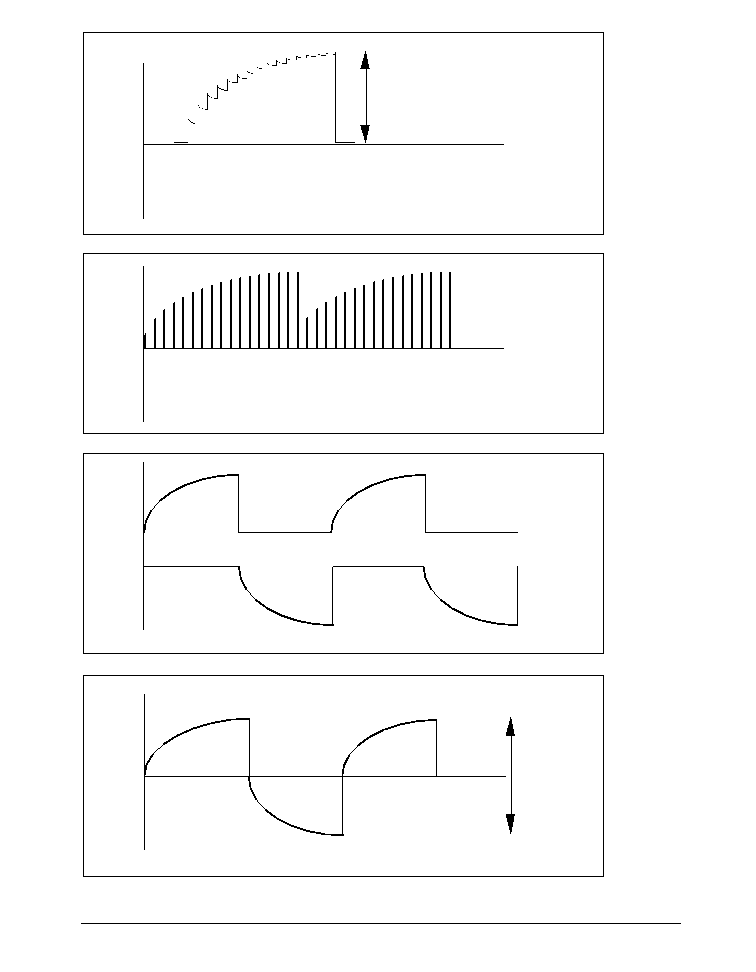
16 coil pulses per half cycle; 94% duty cycle.
EL1 Output
-EL2 Output
V
PEAK
=80V (typical)
EL1 output; 16 charge steps per half cycle
EL1 Output
-EL2 Output
V
PP
=160V
(typical)
Differential Representation EL
12
.
Figure 1.
Figure 2.
Figure 3
.
Figure 4.
SP4415DS/06
SP4415 Electroluminescent Lamp Driver
© Copyright 1996 Sipex Corporation
8
EL Lamp manufacturers
Leading Edge Ind. Inc.
11578 Encore Circle
Minnetonka, MN 55343
Phone 1-800-845-6992
Midori Mark Ltd.
1-5 Komagata 2-Chome
Taita-Ku 111-0043 Japan
Phone: 81-03-3848-2011
Luminescent Systems inc. (LSI)
101 Etna Road
Lebanon, NH. 03766-9004
Phone: (603) 448-3444
Fax: (603) 448-33452
EL polarizers/transflector
manufacturers
Nitto Denko
Yoshi Shinozuka
56 Nicholson Lane
San Jose, CA. 432-5480
Top Polarizer- NPF F1205DU
Bottom - NPF F4225
or (F4205) P3 w/transflector
Transflector Material
Astra Products
Mark Bogin
P.O. Box 479
Baldwin, NJ 11510
Phone (516)-223-7500
Fax (516)-868-2371
CTC Coils LTD (HK)
Flat L-M 14 Fl, Haribest Ind'l Bldg.
45-47 Au Pul Wan Street
Fo Tan Shatin. N.T., Hong Kong
Phone: 85 2695 4889
Fax: 85 2695 1842
Contact: Alfred Wong cc Marine Au
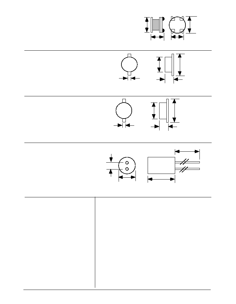
Inductance: 20 mH
±
10%
Resistance: 65 Ohms Max
Model Number: CH5070AS-203K-006
Sipex No. S51208-M-1021-Sipex
2.5
6.5 Max
9.0 Max
25
±
2.0
(All dimensions in mm)
Sankyo Shoji Co. (HK)
RM 28, 9/il Thriving Ind. Centre
Tsuen Wan, N.T.
Hong Kong
Phone: 8522 414 9268
Fax: 8522 413 6040
Contact: Mr. K.M. Chang
Inductance: 29mH
±
20 %
Resistance: 62 Ohms
±
10% @ 25∞C
Part Number SK-121
1.5
3.3
±
0.2
8.1
±
0.2
11.0
±
0.2
(All Dimensions in mm)
Sankyo Shoji Co. (HK)
RM 28, 9/il Thriving Ind. Centre
Tsuen Wan, N.T.
Hong Kong
Phone: 8522 414 9268
Fax: 8522 413 6040
Contact: Mr. K.M. Chang
Inductance: 65mH
±
15mH
Resistance: 270 Ohms
±
15% @ 25∞C
Part Number SK-80
0.8
2.4
5.6
(All Dimensions in mm)
3.6
Max.
7.0
±
0.5
6.0
±
0.3
3.3
±
0.3
6.8
±
0.3
HITACHI METALS Ltd.
Kishimoto Bldg.
2-1, Marunouchi 2-Chome,
Chiyoda-Ku, Tokyo Japan
Phone: 3-3284-4936
Fax: 3-3287-1945
Mr. Noboru Abe
Spec.-
9 mH
±
30% 42 ohm (Max)
Model: MD 735L902B
(All Dimensions in mm)
Singapore
Mr Stan kaiko,
Mr. Hiroshi Kai
Phone: 222-8077
Fax: 222-5232
Hong Kong
Mr Mori Ota
Phone: 2724-4188
Fax: 2311-2095
San Jose, CA
Mr. Kent Oda
Ph: 408 436-9505
Fx: 408 436-9601
Mark Technology: North American stocking distributor for Sankyo and CTC
Phone: 905-891-0165 FAX: 905-891-8534.
NEC Corporation
Yumi Saskai
7-1, Shiba 5 Chome, Minato-ku,
Tokyo 108-01, Japan
Phone: (03) 3798-9572
Fax: (03) 3798-6134
Seiko Precision
Shuzo Abe
1-1, Taihei 4-Chome,
Sumida-ku, Tokyo, 139 Japan
Phone: (03) 5610-7089
Fax: (03) 5610-7177
Gunze Electronics
2113 Wells Branch Parkway
Austin, TX 78728
Phone: (512) 752-1299
Fax: (512) 252-1181
SP4415DS/06
SP4415 Electroluminescent Lamp Driver
© Copyright 1996 Sipex Corporation
9
P
W
1
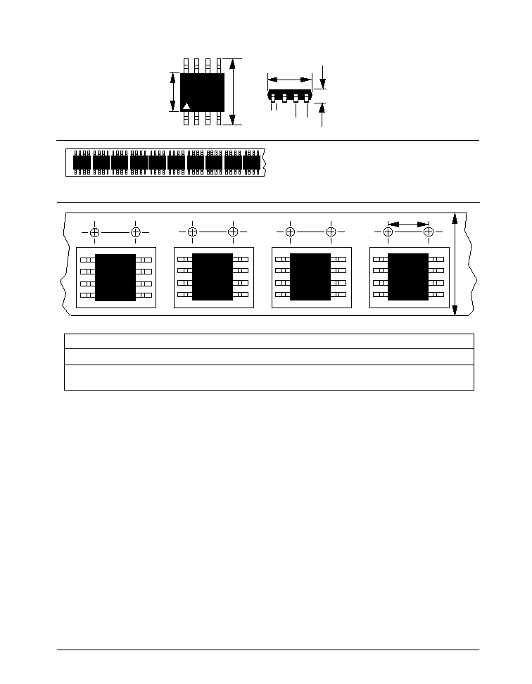
0.228/0.244
0.150/0.157
0.189/0.197
0.014/0.019
0.050 BSC
0.053/0.069
SP4415ACN
Minimum qty per reel
Standard qty per reel
Maximum qty per reel
500
2500
3000
95 SP4415ACN per tube.
NSOIC-8 13" reels: P=8mm, W=12mm
All package dimensions in inches
8-pin NSOIC
SP4415DS/06
SP4415 Electroluminescent Lamp Driver
© Copyright 1996 Sipex Corporation
10
ORDERING INFORMATION
Model
Temperature Range
Package Type
SP4415CN . ............................................. 0∞C to +70∞C ........................................... 8-Pin NSOIC
Corporation
SIGNAL PROCESSING EXCELLENCE
Sipex Corporation reserves the right to make changes to any products described herein. Sipex does not assume any liability arising out of the
application or use of any product or circuit described herein; neither does it convey any license under its patent rights nor the rights of others.
Sipex Corporation
Headquarters and
Sales Office
22 Linnell Circle
Billerica, MA 01821
TEL: (978) 667-8700
FAX: (978) 670-9001
e-mail: sales@sipex.com
Sales Office
233 South Hillview Drive
Milpitas, CA 95035
TEL: (408) 934-7500
FAX: (408) 935-7600
Far East:
JAPAN:
Nippon Sipex Corporation
Yahagi No. 2 Building
3-5-3 Uchikanda, Chiyoda-ku
Tokyo 101
TEL: 81.3.3256.0577
FAX: 81.3.3256.0621
European Sales Offices:
ENGLAND:
Sipex Corporation
2 Linden House
Turk Street
Alton Hampshire GU34 IAN
England
TEL: 44-1420-549527
FAX: 44-1420-542700
e-mail: mikeb@sipex.co.uk
GERMANY:
Sipex GmbH
Gautinger Strasse 10
82319 Starnberg
TEL: 49.81.51.89810
FAX: 49.81.51.29598
e-mail: sipex-starnberg@t-online.de
Please consult the factory for pricing and availability on a Tape-On-Reel option.