1
Date: 6/30/04
SP7611A/7612/7614 Low Dropout LED Driver for Any Color LED © Copyright 2004 Sipex Corporation
FEATURES
LED Drivers for parallel connected LEDs
Ultra Low Dropout Voltage of 150mV
(SP7614)
No EMI, no switching noise
Integrated current matching
PWM and Analog brightness control
Enable/Shutdown control
Shutdown current < 1µA
Small footprint SC-70 Package
Low Dropout LED Driver for any Color LED
Æ
APPLICATIONS
Next Generation Mobile Phones
PDA, DSC, MP3 players
Handheld Computers
LCD Display Modules
Keyboard Backlight
LED Displays
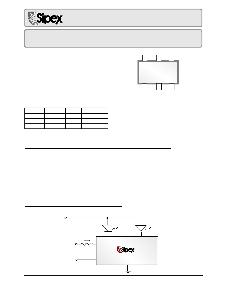
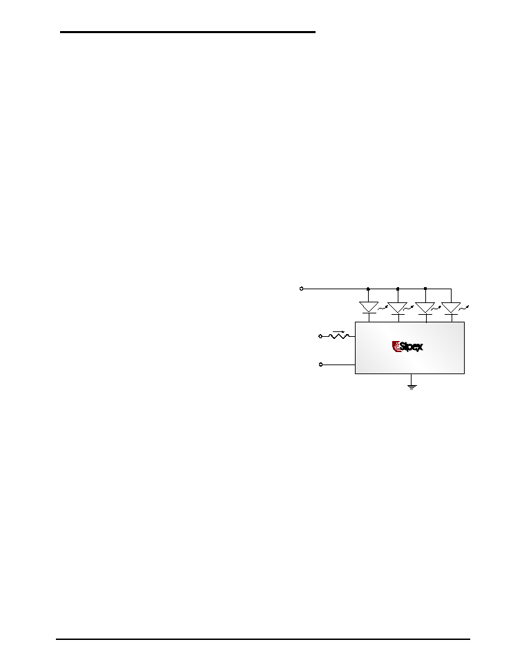
TYPICAL APPLICATION SCHEMATIC
DESCRIPTION
The SP761X driver family provides a simple solution for a matched current source any color LED.
The current in the LEDs can be programmed by an external resistor. The Individual LED currents
are 200 x ISET, where ISET is the current through the external resistor connected to the CTRL
pin. The SP7611A is capable of driving four LEDs, while the SP7612 can drive three LEDs. The
SP7614 is designated to drive two high current LEDs. LED1 should always be connected to an
LED in order to have the other LEDs driven with a matched current to LED1.
The SP7612 and SP7614 have Enable pins. When these devices are disabled, the supply current
drops to 0.01µA typical.
The SP7611A, SP7612 and SP7614 drivers are available in a small footprint 6-pin SC-70
package.
PRELIMINARY
SP7611A/7612/7614
SP7614
6 Pin SC70
1
CTRL
3
N/C
4
GND
2
LED1
6
ON/OFF
5
LED2
Now Available in Lead Free Packaging
VIN
LED1
LED2
GND
CTRL
ON/OFF
ENABLE
VCONTROL
RSET
Æ
Æ
SP7614
I SET
P/N
Channel
I
BIAS
I
BIAS
/LED
SP7611A
4
160
40
SP7612
3
120
40
SP7614
2
160
80
2
Date: 6/30/04
SP7611A/7612/7614 Low Dropout LED Driver for Any Color LED © Copyright 2004 Sipex Corporation
These are stress ratings only and functional operation of the device at these ratings or any other above those indicated
in the operation sections of the specifications below is not implied. Exposure to absolute maximum rating conditions
for extended periods of time may affect reliability.
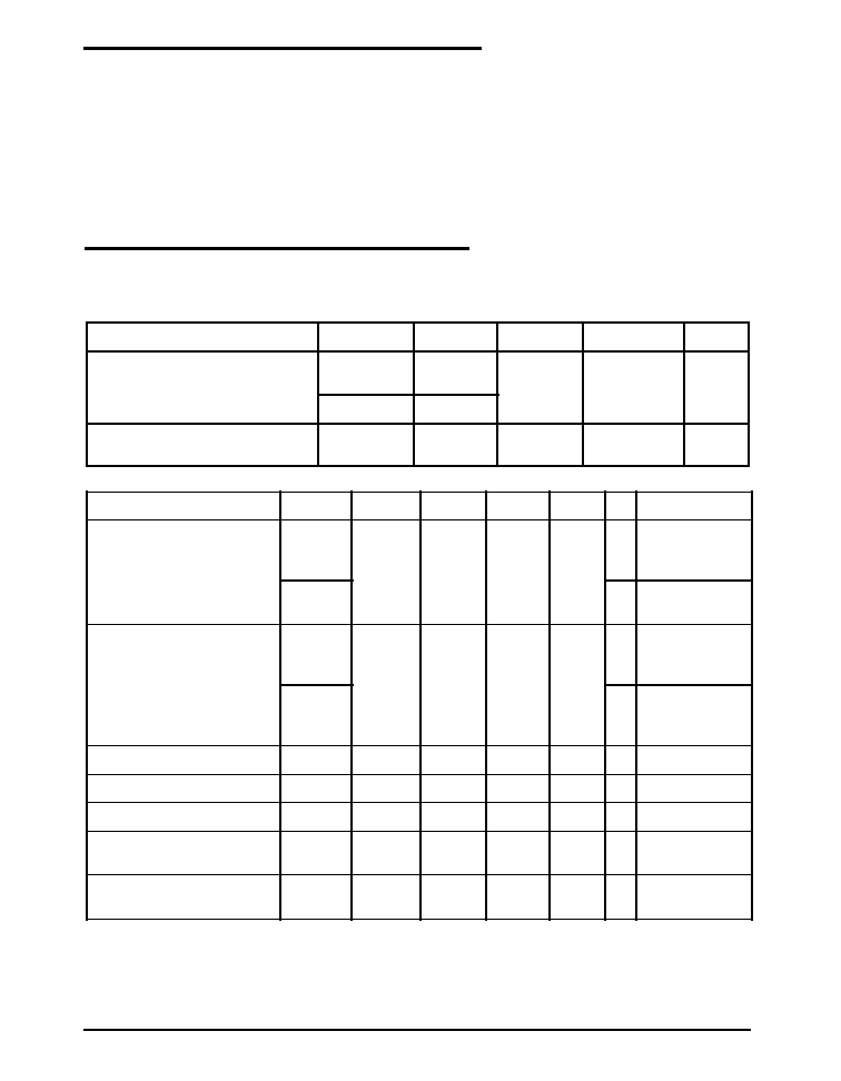
ABSOLUTE MAXIMUM RATINGS
ELECTRICAL CHARACTERISTICS
Specifications are at T
A
=25∞C, V
IN
=3.3to 5.5, ENABLE
=V
IN
,
denotes the specifications which apply over
the full operating temperature range, unless otherwise specified.
V
LED1
, V
LED2
, V
LED3,
V
LED4
and EN Voltage to GND......................................................................................-0.3V to 6V
CTRL Voltage to GND . .........................................................................................................................................0.5V
Output Current (I
OUT
).............................................................................................................................................80mA
Power Dissipation per Package - 6-pin SC-70 at T
A
=85∞C...............................................................................190mW
Junction Temperature.........................................................................................................................................+150∞C
Storage Temperature.......................................................................................................................... -55∞C to +150∞C
ESD Level.
......................................................................................................................................................................................................
4kV HBM
ESD Level.
......................................................................................................................................................................................................
1kV CDM
R
E
T
E
M
A
R
A
P
N
/
P
.
N
I
M
.
P
Y
T
.
X
A
M
S
T
I
N
U
e
g
a
t
l
o
V
e
d
o
h
t
a
C
D
E
L
A
1
1
6
7
P
S
2
1
6
7
P
S
3
.
0
5
.
0
1
V
4
1
6
7
P
S
5
1
.
0
e
r
u
t
a
r
e
p
m
e
T
t
n
e
i
b
m
A
4
1
6
7
P
S
0
4
-
0
2
5
8
C
∫
R
E
T
E
M
A
R
A
P
N
/
P
.
N
I
M
.
P
Y
T
.
X
A
M
S
T
I
N
U
S
N
O
I
T
I
D
N
O
C
n
o
i
t
a
c
il
p
i
t
l
u
M
t
n
e
r
r
u
C
t
u
p
t
u
O
)
1
e
t
o
N
(
o
i
t
a
R
A
1
1
6
7
P
S
2
1
6
7
P
S
0
4
1
0
0
2
0
6
2
I
T
E
S
A
µ
0
0
1
=
V
T
A
S
V
m
0
0
3
=
4
1
6
7
P
S
I
T
E
S
A
µ
0
0
1
=
V
T
A
S
V
m
0
5
1
=
I
t
n
e
r
r
u
C
D
E
L
D
E
L
)
e
d
o
i
D
r
e
P
(
A
1
1
6
7
P
S
2
1
6
7
P
S
0
2
A
m
I
T
E
S
A
µ
0
0
1
=
V
T
A
S
V
m
0
0
3
=
4
1
6
7
P
S
I
T
E
S
A
µ
0
0
1
=
V
T
A
S
V
m
0
5
1
=
g
n
i
h
c
t
a
M
t
n
e
r
r
u
C
D
E
L
o
t
D
E
L
3
-
8
.
0
3
%
d
a
o
L
o
N
y
c
n
e
i
c
i
f
f
E
k
a
e
P
0
9
%
V
N
I
V
3
=
e
d
o
M
F
F
O
n
i
t
n
e
r
r
u
C
1
0
.
0
1
A
µ
V
N
E
V
0
=
"
e
g
a
t
l
o
V
N
O
"
E
L
B
A
N
E
.
n
i
M
2
1
6
7
P
S
4
1
6
7
P
S
3
V
I
T
E
S
A
µ
0
5
1
=
"
e
g
a
t
l
o
V
F
F
O
"
E
L
B
A
N
E
.
x
a
M
2
1
6
7
P
S
4
1
6
7
P
S
5
.
0
V
Note 1: Output current Multiplication Ratio (I
LED
/I
SET
) is not linear. For actual ratio and I
LED
please refer to typical
performance characteristics @ page 4.
3
Date: 6/30/04
SP7611A/7612/7614 Low Dropout LED Driver for Any Color LED © Copyright 2004 Sipex Corporation
PIN DESCRIPTION
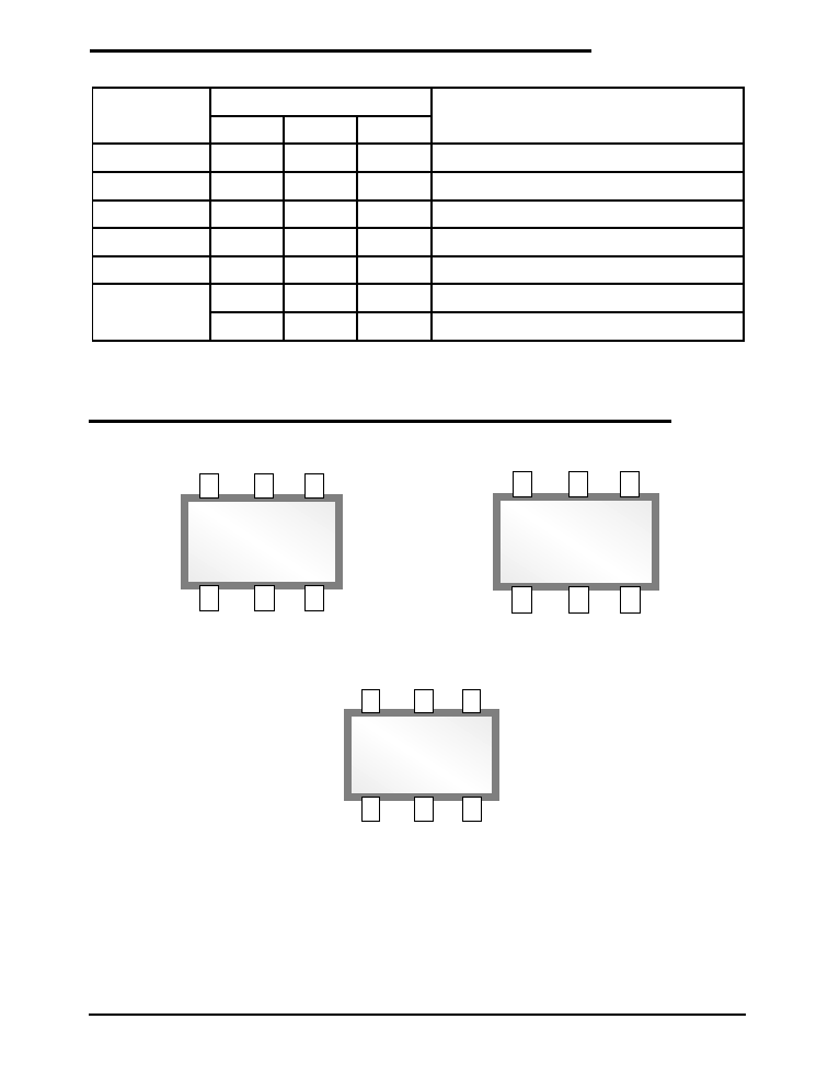
PINOUT
SP7614
6 Pin SC70
1
CTRL
3
N/C
4
GND
2
LED1
6
ON/OFF
5
LED2
SP7612
6 Pin SC70
1
CTRL
3
LED1
4
GND
2
LED2
6
ON/OFF
5
LED3
SP7611A
6 Pin SC70
1
CTRL
3
LED1
4
GND
2
LED2
6
LED3
5
LED4
.
o
N
n
i
P
E
M
A
N
N
I
P
N
O
I
T
P
I
R
C
S
E
D
A
1
1
6
7
P
S
2
1
6
7
P
S
4
1
6
7
P
S
1
L
R
T
C
L
R
T
C
L
R
T
C
t
n
e
r
r
u
C
D
E
L
s
t
e
S
2
2
D
E
L
2
D
E
L
1
D
E
L
D
E
L
f
o
e
d
o
h
t
a
C
o
t
t
c
e
n
n
o
C
3
1
D
E
L
1
D
E
L
C
N
D
E
L
f
o
e
d
o
h
t
a
C
o
t
t
c
e
n
n
o
C
4
D
N
G
D
N
G
D
N
G
d
n
u
o
r
G
5
4
D
E
L
3
D
E
L
2
D
E
L
D
E
L
f
o
e
d
o
h
t
a
C
o
t
t
c
e
n
n
o
C
6
3
D
E
L
D
E
L
f
o
e
d
o
h
t
a
C
o
t
t
c
e
n
n
o
C
F
F
O
/
N
O
F
F
O
/
N
O
e
l
b
a
s
i
D
/
F
F
O
/
N
O
p
i
h
C
4
Date: 6/30/04
SP7611A/7612/7614 Low Dropout LED Driver for Any Color LED © Copyright 2004 Sipex Corporation
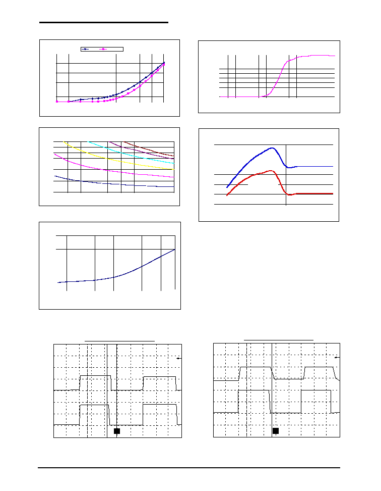
TYPICAL PERFORMANCE CHARACTERISTICS
LED Current versus Enable Voltage
0.000
2.000
4.000
6.000
8.000
10.000
12.000
14.000
16.000
18.000
VEN Voltage (V)
LED Current (mA)
ILED vs Set Resistor and Cathode Voltage
2.0
4.0
6.0
8.0
10.0
12.0
14.0
16.0
18.0
20.0
10
20
30
40
50
60
70
80
90
100
Set Resistor (kOhms)
LED Current (mA)
Vk=50mV
Vk=100mV
Vk=150mV
Vk=200mV
Vk=250mV
Vk=300mV
PWM LED Current vs. Temperature
21
22
23
24
25
-40 -30 -20 -10
0
10
20
30
40
50
60
70
80
Temperature (C)
ILED(mA)
Iset=100uA, Vcathode=150mV
T
T
[
]
T
Time (1µs/div)
CTRL V
oltage
LED
Current
(1V/div)
(20mA/div)
T
T
[
]
T
CTRL V
oltage
LED
Current
(1V/div)
(20mA/div)
Time (1µs/div)
Enable Voltage Transient Response
Control Voltage Transient Response
SP7614 LED Current vs. LED Cathode Voltage
5
10
15
20
25
30
35
0
0.2
0.4
0.6
0.8
1
LED Cathode Voltage (V)
LED Current (mA)
For Iset = 25uA
For Iset = 50uA
ISET versus CTRL Voltage
0.0
20.0
40.0
60.0
80.0
100.0
120.0
140.0
160.0
180.0
200.0
0.00
0.20
0.40
0.60
0.80
1.00
1.20
1.40
1.60
1.80
CTRL Pin Voltage (V)
Set Current (µA)
Vk=1V
Vk=150mV
5
Date: 6/30/04
SP7611A/7612/7614 Low Dropout LED Driver for Any Color LED © Copyright 2004 Sipex Corporation
APPLICATION INFORMATION
SETTING THE LED CURRENT
The current flowing into LEDs is approximately 200
times greater than the current I
SET
. The LED current is
controlled by
I
CONTROL
and R
SET
according to the follow-
ing formula
:
I
LED
= 200 X (V
CONTROL
- V
CTRL
)
/ R
SET
For V
CONTROL
= 3V and a specified LED current, the R
SET
value can be evaluated using the diagram shown in the
Typical Performance Characteristics section. For any
other option, I
SET
vs. V
CTRL.
The LED's brightness can
also be adjusted by driving ENABLE or the CTRL pin with
a PWM signal. The driving signal frequency should be
greater than 100Hz to avoid flickering, increasing to
more than 1MHz, if necessary.
LEDs are very sensitive to temperature. In most cases
the maximum allowed junction temperature is 100∫C.
This temperature is the result of adding to the ambient
temperature the over temperature due to power dissipa-
tion, is described by the following:
T
j
= T
A
+ ÿ
jA
x I xV
F
where T
j
is the LED junction temperature, T
A
is the
ambient temperature, ÿ
jA
is the junction to ambient
thermal resistance, I is the LED current and V
F
is the LED
forward voltage
.
The SP7611AA to SP7614 are designed to reduce the
current through LEDs, when the temperature rises and
the cathode voltage increases, as can be seen from
typical the "LED Current vs. LED Cathode Voltage"
graph under the Typical Performance Characteristics
section.
The SP761X driver's low dropout architecture can sig-
nificantly improve the efficiency compared to using simple
ballast resistors.
The system efficiency, defined as the ratio between the
LEDs power and the input supplied power can be
calculated as follows:
Efficiency = (V
IN
- V
CATHODE
)
/ V
IN
The lower the V
CATHODE
, the higher the system effi-
ciency. Efficiency can be further improved using a higher
V
IN
with more LEDs as shown in example 3.
APPLICATION NOTES
The ultra-low voltage drop across the SP761X series of
LED drivers, allow the devices to drive white, blue, and
other color LEDs in a wide range of input voltages. The
driver can be used in many applications. Although, only
the SP7611A is shown in all three examples, any of the
SP762X series of LED drivers can be used in the
applications presented in this document, due to their
similar operation.
Example 1: Drive low V
F
white or blue LEDs directly
from single cell Li-ion
When using white or blue low V
F
LEDs, and utilizing the
drivers low voltage drop, only 3.4V in V
IN
is needed for the
full 20mA LED current. At 3.1V, there is still 5mA typical
current available for the LEDs. The single cell Li-ion is
utilized in most applications like cell phones or digital still
cameras. In most cases, the Li-ion battery voltage level
only goes down to 3.0V voltage level, and not down to the
full discharge level (2.7V) before requesting the charger.
- T
DROP
< 0.3V
- V
F
(at 20mA) < 3.1V (Low V
F
)
- V
IN
(at 20mA) < - V
DROP
+V
F
= 3.4V
- V
IN
(at 5mA typical) ~ 3.1V
Key Advantages
1) No boost circuit needed for the LCD or keyboard
backlight
2) Drivers directly connected to a Li-ion battery
3) No EMI, no switching noise, no boost efficiency lost,
no capacitor, and no inductor
VIN
LED1
GND
CTRL
ON/OFF
ENABLE
VCONTROL
RSET
Æ
Æ
SP7611
I SET
LED3
LED2
LED4