Rev. 10/25/00
Precision Micropower 1.24V Shunt Voltage Reference
FEATURES
APPLICATIONS
∑
Low temperature coefficient 50 ppm/∞C
∑
Constant Current Source
∑
Operating current range 100
µA to 15 mA
∑
Digital Voltmeter
∑
Low power, 250 mW @ I
IN
=100
mA
∑
Power Supply Monitor
∑
Two terminal "Zener" operation
∑
Precision Regulators
∑
Small package: SOT - 23, TO-92, and SO-8
∑
Battery-Powered Equipment
∑
Fixed reverse breakdown voltage 2.5 Volt
∑
Instrumentation
∑
No output capacitance required
∑
Automotive Electronics
∑
Output voltage tolerance
±
0.5%
∑
Data Acquisition Systems
∑
Energy Management
PRODUCT DESCRIPTION
The SPX4041 is a two-terminal, temperature compensated, band-gap voltage reference, which provides a fixed 1.24V output for input
currents between 500
µA to 5mA. The bandgap voltage (1.24V) is independently laser trimmed from the output voltage to achieve a
very low tempco, then the output voltage is laser trimmed to 1.24 volts. This trimming technique and the low tempco (A grade 50
ppm/
∞C) thin film resistor process gives a very stable device over the full temperature range. The SPX4041 is available in the sub-
miniature (3mm
◊ 1.3mm) SOT-23, SO-8 surface mount package, or TO-92 package. The operating temperature is -40∞C to 85∞C.
The SPX4041 advanced design eliminates the need for an external stabilized capacitor while insuring stability with any capacitive
load, making them easy to use.
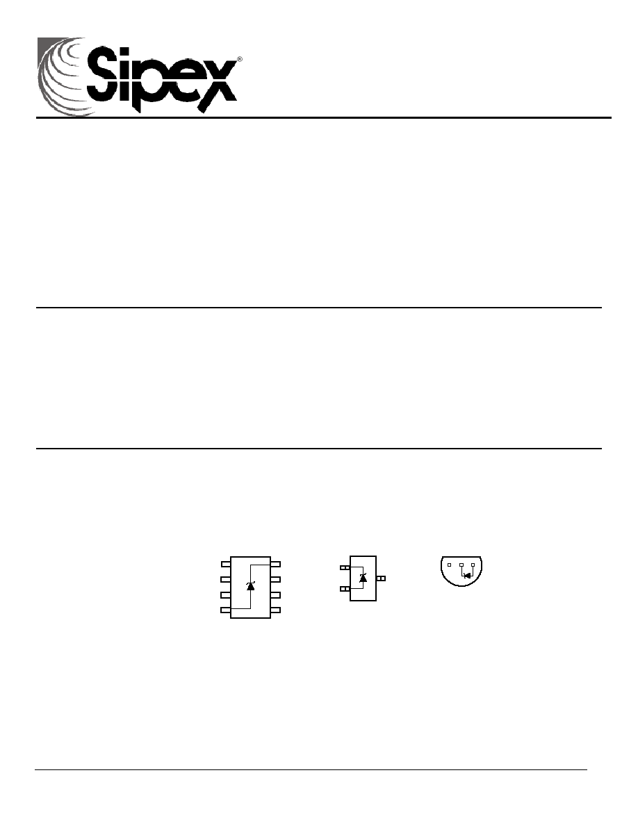
PIN CONNECTIONS
Top View
2
1
3
4
8
7
6
5
8-Pin Surface Mount (S)
SOT-23-3 (M)
Top View
2
3
+
-
1
Bottom View
TO-92 (N)
1
3
2
N/C
N/C
N/C
-
N/C
N/C
N/C
+
SPX4041
Rev. 10/25/00
SPX4041
ABSOLUTE MAXIMUM RATINGS
Reverse Current................................................................20mA
Power Dissipation at 25
∞C
Forward
Current ...............................................................10mA M
Package ...................................................... 300mW
Storage Temperature ...................................... -65
∞C to +150∞C N
Package ....................................................... 550mW
Lead Temperature (Soldering) ........................................ 300
∞C S
Package........................................................ 525mW
Temperature
Range ................................... -40
∞C T
A
+85∞C
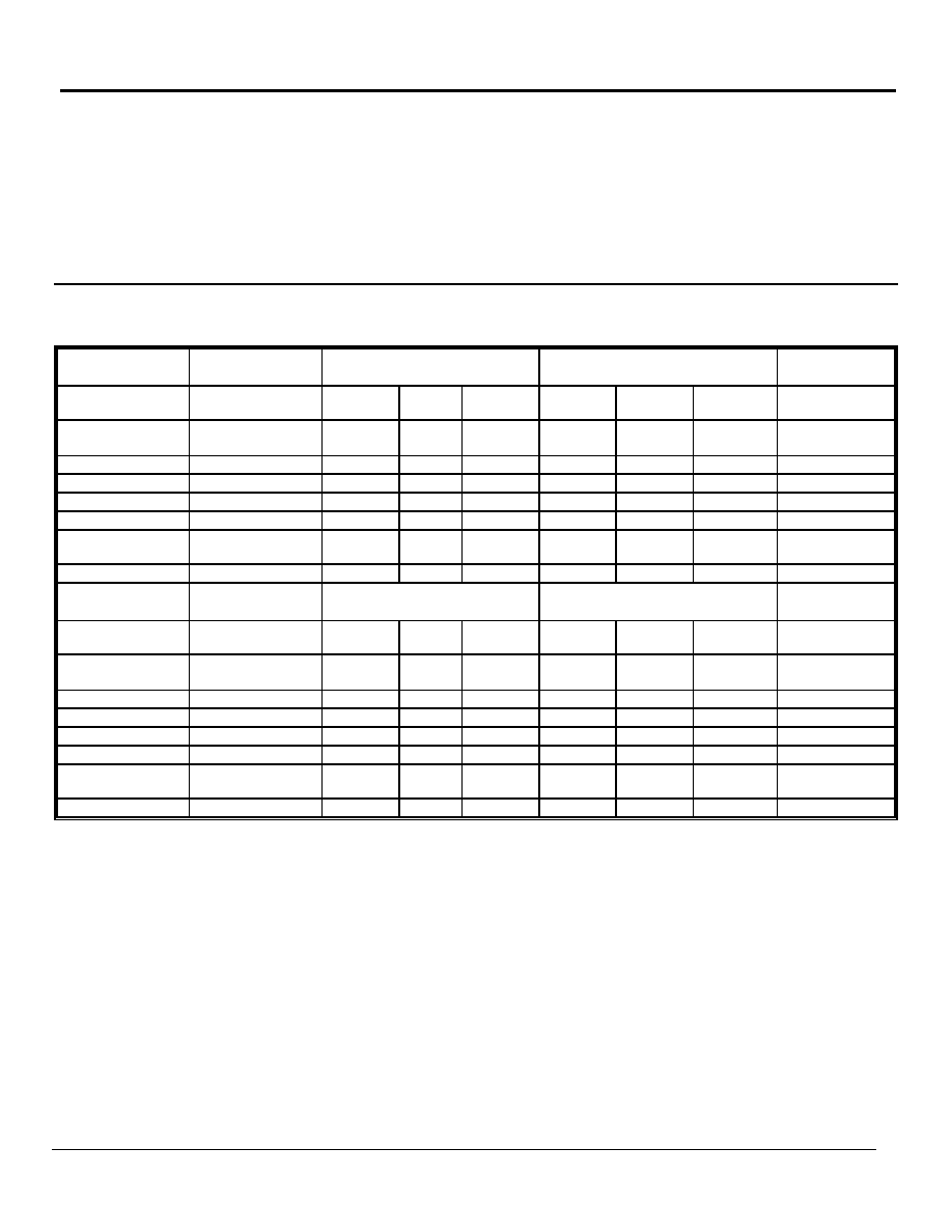
ELECTRICAL CHARACTERISTICS
Electrical Characteristics at I
IN
= 1000
µA, and T
A
= +25∞C unless otherwise noted. . Boldface limits apply over temperature.
Parameters
Conditions
SPX4041A2
Min Typ Max
SPX4041B2
Min Typ Max
Units
Reverse Breakdown
Voltage
I
R
=500
µA
1.24
1.24
V
Reverse Breakdown
Tolerance
I
R
=500
µA
±25
±49
±25
±49
mV
mV
Output
Impedance
0.60
2 0.60 2
Noise Voltage
0.1kHz
f 10Hz
15 15
µV p-p
Tempco
Note
1
50 100 ppm/∞C
Turn-on Setting
0.1% of V
OUT
30
30
µSec
Operating Current
Range
Note 2
0.5
5
15
0.5 5
15
mA
Temp.
Range
-40 85 -40 85
∞C
Parameters
Conditions
SPX4041A3
Min Typ Max
SPX4041B3
Min Typ Max
Units
Reverse Breakdown
Voltage
I
R
=500
µA
1.24
1.24
V
Reverse Breakdown
Tolerance
I
R
=500
µA
±50
±74
±50
±74
mV
mV
Output
Impedance
0.60
2 0.60 2
Noise Voltage
0.1kHz
f 10Hz
15 15
µV p-p
Tempco
Note
1
50 100 ppm/∞C
Turn-on Setting
0.1% of V
OUT
30
30
µSec
Operating Current
Range
Note 2
0.1
5
15
0.1 5
15
mA
Temp.
Range
-40 85 -40 85
∞C
Rev. 10/25/00
SPX4041
Note:
1) Three-point measurement guarantees the error band over the specified temperature range.
2) Optimum performance is obtained at currents below 1000
µA.
3) Limits are 100% production tested at 25
∞C. Limits over temperature are guaranteed through correlation using statistical quality
control.
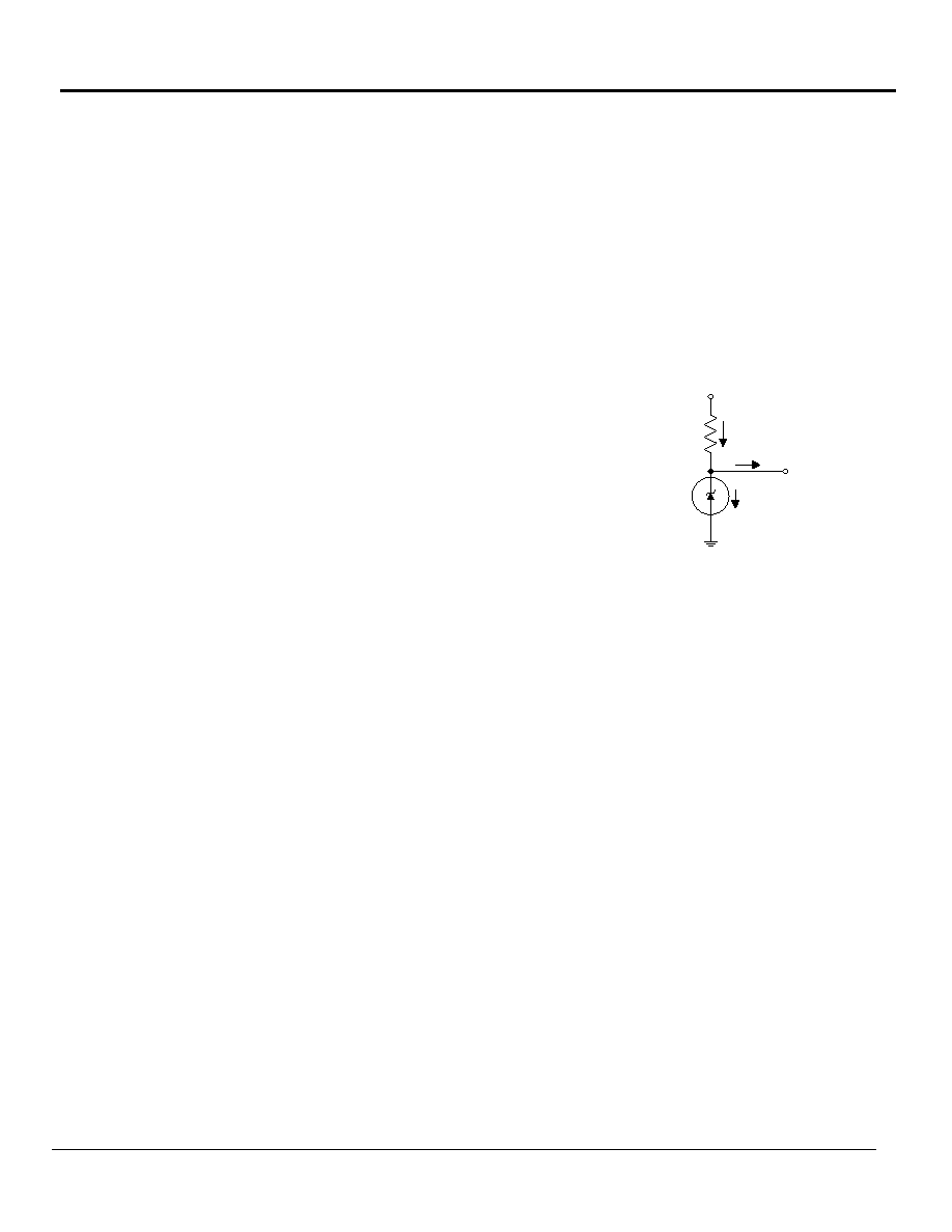
SPX4041 Applications Hints
This device is designed for stable operation and has no need
of an external capacitor between pin 4 and 8. The reference
remains stable if a bypass capacitor is used.
SOT-23
The SPX4041 in the SOT-23 package has a parasitic
Schottky diode between pin 3 and pin 1. Pin 1 of SOT-23
must float or be connected to pin 3.
Conventional Shunt Regulator
In a conventional shunt regulator application (see Figure 1),
an external series resister (R
S
) is connected between the
supply voltage and the SPX4041. R
S
determines the current
that flows through the load (I
L
) and the reference(I
Q
). Since
load current and supply voltage may vary, R
S
should be small
enough to supply at least the minimum acceptable I
Q
to the
reference even when the supply voltage is at its minimum and
the load current is at its maximum value. When the supply
voltage is at its maximum and I
L
is at its minimum, R
S
should
be large enough so that the current flowing through the
SPX4041-x.x is less than 15mA
R
S
is determined by the supply voltage (V
S
), the load and
operating current (I
L
and I
Q
), reference's reverse breakdown
voltage (V
R
).
R
S
= (V
S
- V
R
)/(I
L
+I
Q
)
Figure 1. SPX4041 Fixed
Shunt Regulator Application
V
S
R
S
V
R
I
L
I
Q
I
O
+ I
L
V
O
SPX4041
Rev. 10/25/00
SPX4041
DRAWING PACKAGE
8-PIN SOIC (S)
Pin 1
1.27 (0.50)
BSC
3.8 (0.150)
4.0 (0.158)
4.6 (0.181)
5.2 (0.205)
5.8 (0.228)
6.2 (0.244)
4.8 (0.188)
5.0 (0.197)
0.49 (0.019)
0.56 (0.022)
0.35 (0.014)
0.45 (0.018)
0.10 (0.004)
0.20 (0.008)
0.19 (0.007)
0.22 (0.009)
1.35 (0.053)
1.75 (0.069)
0.61 (0.024)
0.78 (0.031)
3
∞-6∞
0.64 (0.025)
0.77 (0.030)
45
∞
7
∞(4 PLCS)
7
∞(4 PLCS)
0.37 (0.015)
BSC
Rev. 10/25/00
SPX4041
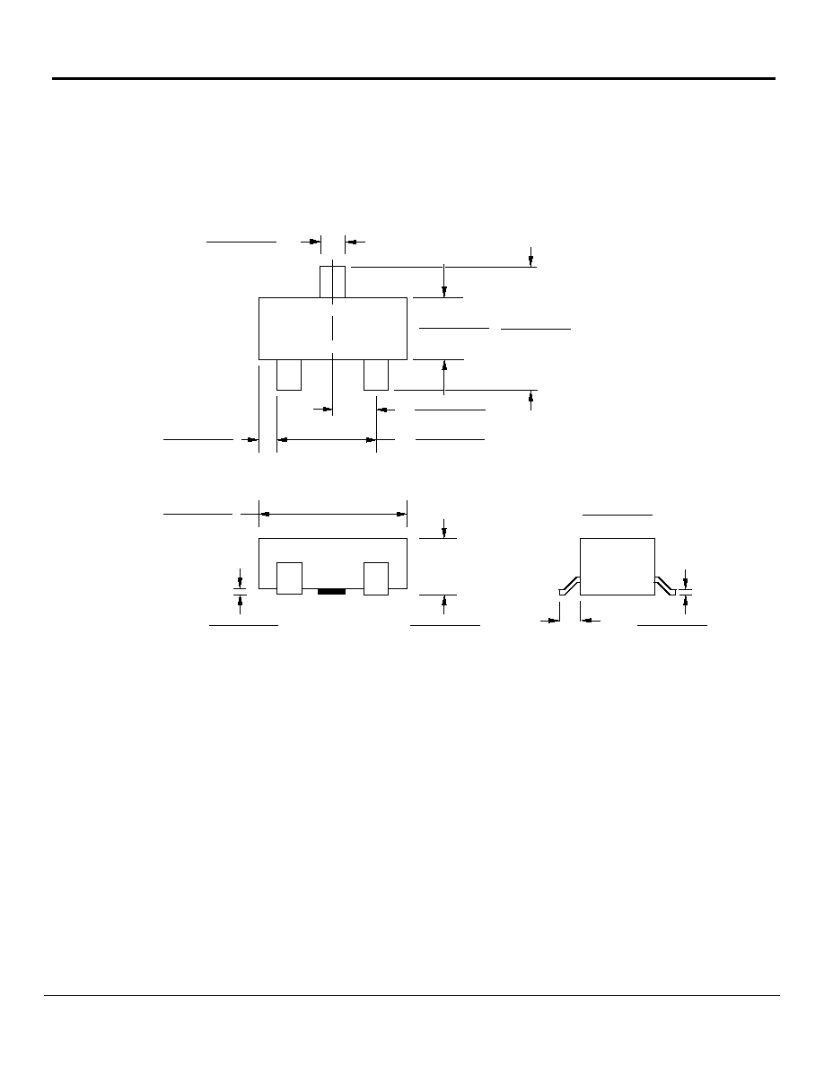
DRAWING PACKAGE
SOT-23-3L (M)
0.015 - 0.018
(0.381 - 0.457)
0.020 - 0.024
(0.508 - 0.610)
0.110 - 0.120
(2.794 - 3.048)
0.001 - 0.004
(0.025 - 0.102)
0.030 - 0.041
(0.762 - 1.041)
0.018 - 0.024
(0.457 - 0.610)
0.070 - 0.080
(1.778 - 2.032)
0.035 - 0.040
(0.889 - 1.016)
0.047 - 0.055
(1.194 - 1.397)
0.083 - 0.098
(2.108 - 2.489)
0.003 - 0.005
(0.076 - 0.127)