Skyworks Solutions, Inc. [978] 241-7000
∑ Fax [978] 241-7906 ∑ Email sales@skyworksinc.com ∑ www.skyworksinc.com
1
Specifications subject to change without notice. 12/02A
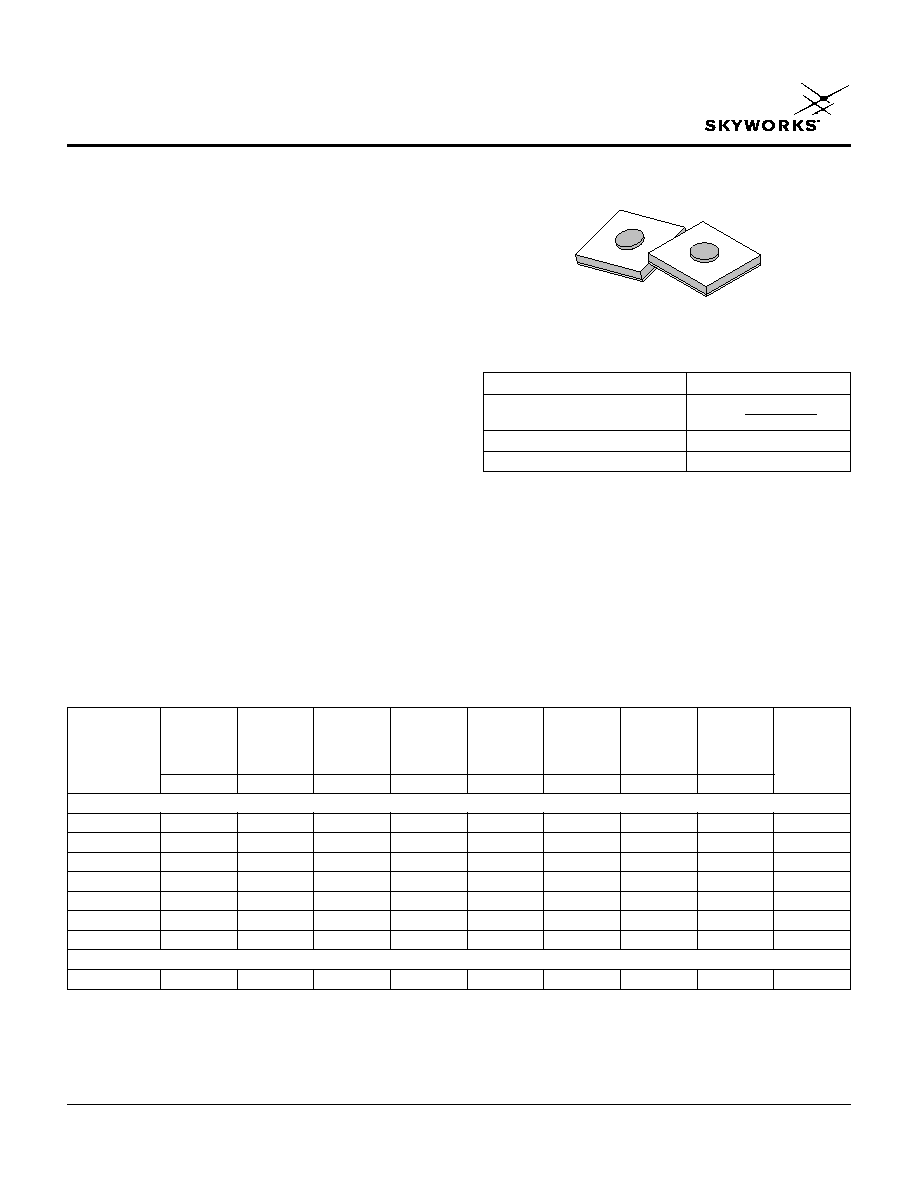
Silicon PIN Diode Chips
Features
Established Alpha PIN Diode Process
For Switch and Attenuator Applications
Low Capacitance Designs to 0.05 pF
Voltage Ratings to 200 V
Chip Size Smaller than 15 Mils Square
APD Series
Description
Alpha's APD Series of silicon PIN diode chips are
designed for use as switch and attenuator devices in high
performance hybrid microwave integrated circuits. These
PIN diode designs are useful over a wide range of
frequencies from below 100 MHz to beyond 30 GHz.
These devices utilize Alpha's well established silicon
technology resulting in high resistivity and tightly
controlled I region width PIN diodes. APD0505-00
through APD1510-000 are primarily designed for fast
speed through moderate speed switch applications. They
have low resistance and capacitance at zero bias and
reverse bias. The thick I region APD2220-000 is primarily
designed for low distortion attenuator applications.
Capacitance Capacitance
R
S
Voltage
V
R
= 50 V,
V
R
= 0 V,
I = 10 mA,
TL
Rating
Thermal
Contact
Part Number
1 MHz
1 MHz
500 MHz
I = 10 mA
I
R
= 10
µ
µA
I Region
Resistance
Diameter
Outline
(pF)
(pF)
(
)
(ns)
(V)
(
µ
µM)
(Cc/W)
(Mils)
Drawing
Max.
Typ.
Max.
Typ.
Min.
Nom.
Max.
Nom.
Switching Applications
APD0505-000
0.05
0.10
2.0
20
50
5
100
1.5
150-806
APD0510-000
0.10
0.20
1.5
40
50
5
80
2.5
150-801
APD0520-000
0.20
0.25
1.0
50
50
5
80
3.5
150-801
APD0805-000
0.05
0.10
2.0
100
100
8
80
2.0
150-801
APD0810-000
0.10
0.15
1.5
160
100
8
60
3.0
150-801
APD1510-000
0.10
0.20
2.0
300
200
15
60
3.0
150-801
APD1520-000
0.20
0.25
1.2
400
200
15
30
4.0
150-802
Attenuator Applications
APD2220-000
0.20
0.20
4.0
100
100
50
80
7.5
149-815
Electrical Specifications at 25∞C
Characteristic
Value
Power Dissipation
Pdiss = W
Operating Temperature
-65∞C to +175∞C
Storage Temperature
-65∞C to +200∞C
Absolute Maximum Ratings
175-
Tamb

Silicon PIN Diode Chips
APD Series
2
Skyworks Solutions, Inc. [978] 241-7000
∑ Fax [978] 241-7906 ∑ Email sales@skyworksinc.com ∑ www.skyworksinc.com
Specifications subject to change without notice. 12/02A
0.014 ± 0.001
(0.350 ± 0.025 mm)
0.014 ± 0.001
(0.350 ± 0.025 mm)
CATHODE METALIZED BACK
CONTACT GOLD
ANODE
METALIZED
GOLD DOT
0.002 (0.051 mm)
MIN. DIA.
0.004 (0.127 mm) MIN.
0.006 (0.152 mm) MAX.
Outline Drawings
149-815
ANODE
METALIZED
GOLD DOT
SILICON
CATHODE METALIZED BACK
CONTACT GOLD
0.004 (0.127 mm) MIN.
0.006 (0.152 mm) MAX.
0.010 (0.251 mm) MIN.
0.014 (0.356 mm) MAX. SQ.
150-801:
0.002 (0.051 mm) MIN.
150-806:
0.0011 (0.028 mm) MIN.
150 Series
Description
Symbol
APD0505-000 APD0510-000
APD0805-000
APD0810-000
APD1510-000
APD2220-000
Unit
Saturation Current
IS
6.40E-14
5.50E-17
1.20E-11
1.50E-12
1.60E-10
2.00E-09
A
Series Resistance
R
S
0.25
0.50
1.00
0.30
1.00
0.20
Emission Coefficient
N
1.40
1.02
1.70
1.48
1.80
1.90
Reverse Breakdown
B
V
50.00
50.00
100.00
100.00
200.00
200.00
V
Current at B
V
I
BV
10E-06
10E-06
10E-06
10E-06
10E-06
10E-06
A
Zero Bias Capacitance
C
J0
0.12E-12
0.18E-12
0.13E-12
0.16E-12
0.25E-12
0.2E-12
F
Junction Potential
V
J
1.00
1.00
1.00
1.00
1.00
1.00
V
Grading Coefficient
M
0.50
0.50
0.50
0.50
0.50
0.50
Transit Time
TT
20E-9
40E-9
50E-9
160E-9
300E-9
400E-9
s
SPICE Model Parameters
Typical Performance Data
Resistance (
)
Forward Current (mA)
Resistance vs. Forward Current @ 1 GHz
0.1
1
10
100
1000
0.01
0.1
1
10
100
APD0505-000
APD0510-000
APD0805-000
Resistance (
)
Forward Current (mA)
Resistance vs. Forward Current @ 1 GHz
0.1
1
10
100
1000
0.01
0.1
1
10
100
APD0810-000
APD1510-000
APD2220-000