Äîêóìåíòàöèÿ è îïèñàíèÿ www.docs.chipfind.ru
Skyworks Solutions, Inc. · Phone [781] 376-3000 · Fax [781] 376-3100 · sales@skyworksinc.com · www.skyworksinc.com
101944B · Skyworks Proprietary and Confidential Information · Products and Product Information are Subject to Change Without Notice. · July 28, 2004
1
DATA SHEET
CX77304-16 PA Module for Tri-Band EGSM DCS PCS / GPRS
Applications
· Tri-band cellular handsets
encompassing
-
Class 4 EGSM900
-
Class 1 DCS1800
-
PCS1900, and
-
Up to Class 10 GPRS
multislot operation
Features
· High efficiency
-
EGSM 55%
-
DCS 50%
-
PCS 45%
· Input/output internally
matched to 50
· Small outline
-
9.1 mm
× 11.6 mm
· Low profile
-
1.5 mm
· Low APC current
-
10
µA typical
· Gold plated, lead-free
contacts
Description
The CX77304-16 Power Amplifier Module (PAM) is designed in a compact form factor for tri-band
cellular handsets comprising EGSM900, DCS1800, and PCS1900 operation. It also supports Class 10
General Packet Radio Service (GPRS) multislot operation.
The PAM consists of separate Heterojunction Bipolar Transistor (HBT) PA blocks for EGSM900 and
DCS1800/PCS1900 PA bands, interface circuitry, and RF input and output ports internally matched to
50 W to reduce the number of external components. The PA blocks are fabricated on a single Gallium
Arsenide (GaAs) die. Optimized for lithium ion battery operation, both PA blocks share common power
supply pins to distribute current. Extremely low leakage current (2 µA, typical) of the dual PAM
maximizes handset standby time.
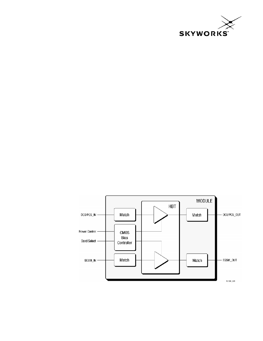
The CX77304-16 also contains band-select switching circuitry to select EGSM (logic 0) and DCS/PCS
(logic 1) as determined from the Band Select (BS) signal. In the block diagram shown below, the BS
pin selects the PA output (DCS/PCS OUT or EGSM OUT) while the Analog Power Control (APC) controls
the level of output power.
A custom CMOS integrated circuit provides the internal interface circuitry including a current amplifier
that minimizes the required power control current (IAPC) to 10 µA, typical. The GaAs die, the Silicon
(Si) die, and passive components are mounted on a multi-layer laminate substrate and the assembly
encapsulated with plastic overmold.
Figure 1. Functional Block Diagram
DATA SHEET · CX77304-16
PA MODULE FOR TRI-BAND EGSM DCS PCS / GPRS
Skyworks Solutions, Inc. · Phone [781] 376-3000 · Fax [781] 376-3100 · sales@skyworksinc.com · www.skyworksinc.com
2
July 28, 2004 · Skyworks Proprietary and Confidential Information · Products and Product Information are Subject to Change Without Notice. · 101944B
Electrical Specifications
The following tables list the electrical characteristics of the
CX77304-16 Power Amplifier.
Table 1
lists the absolute maximum
ratings and
Table 2
shows the recommended operating
conditions.
Table 3
shows the electrical characteristics of the
CX77304-16 for EGSM, DCS, and PCS modes. A typical
CX77304-16 application schematic appears in
Figure 2
.
The CX77304-16 is a static-sensitive electronic device and should
not be stored or operated near strong electrostatic fields. Detailed
ESD precautions along with information on device dimensions, pin
descriptions, packaging and handling can be found in later
sections of this data sheet.
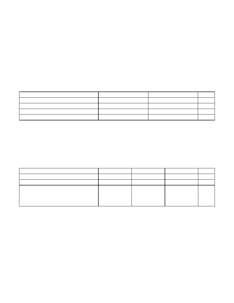
Table 1. Absolute Maximum Ratings
Parameter Minimum
Maximum
Unit
Input Power (P
IN
) --
15
dBm
Supply Voltage (V
CC
), Standby, V
APC
0.3 V
--
7
V
Control Voltage (V
APC
) 0.5
V
CC_MAX
0.2 (See Table 3)
V
Storage Temperature
55
+100
°C
Table 2. Recommended Operating Conditions
(1)
Parameter Minimum
Typical
Maximum
Unit
Supply Voltage (V
CC
) 2.9
3.5
4.8
(1)
V
Supply Current (I
CC
) 0.0
2.5
(1)
A
Operating Case Temperature (T
CASE
)
1-Slot (12.5% duty cycle)
2-Slot (25% duty cycle)
3-Slot (37.5% duty cycle)
4-Slot ( 50% duty cycle)
20
20
20
20
100
90
75
60
°C
(1) For charging conditions with V
CC
> 4.8 V, derate I
CC
linearly down to 0.5 A max at V
CC
= 5.5 V.
PA MODULE FOR TRI-BAND EGSM DCS PCS / GPRS
DATA SHEET · CX77304-16
Skyworks Solutions, Inc. · Phone [781] 376-3000 · Fax [781] 376-3100 · sales@skyworksinc.com · www.skyworksinc.com
101944B · Skyworks Proprietary and Confidential Information · Products and Product Information are Subject to Change Without Notice. · July 28, 2004
3
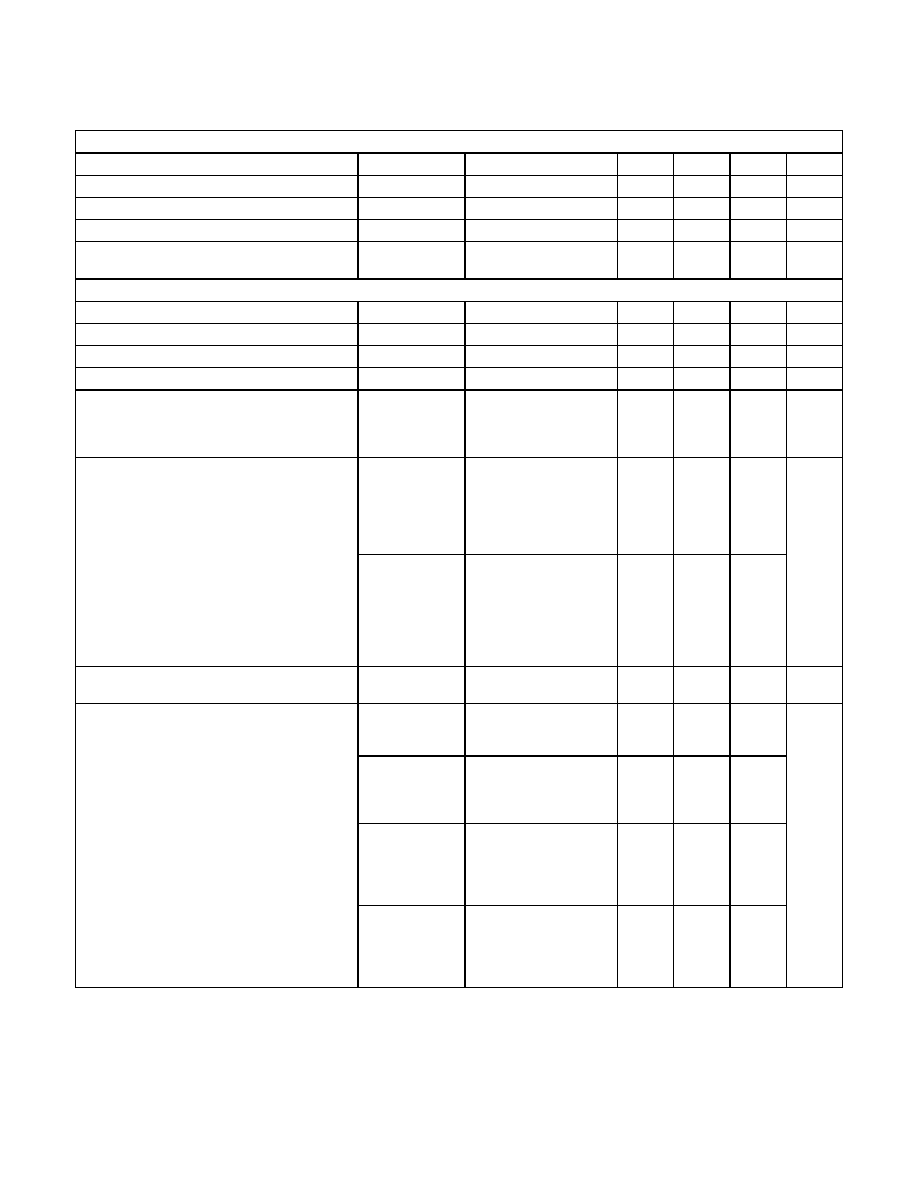
Table 3. CX77304-16 Electrical Specifications
(1)
(1 of 6)
General
Parameter Symbol
Test
Condition
Minimum
Typical
Maximum
Units
Power control current
l
APC
--
--
10
100
mA
Supply voltage
V
CC
--
2.9 3.5 4.8 V
APC Enable Threshold
V
APC_TH
--
200
--
600
mV
APC Enable Switching Delay
t
SW
Time from V
APC
V
APC_TH
until
P
OUT
(P
OUT_FINAL
3 dB)
5 8 µs
EGSM900 Mode (f = 880 to 915 MHz and P
IN
= 7 to 12 dBm)
Parameter Symbol
Test
Condition
Minimum
Typical
Maximum
Units
Frequency range
f
--
880
--
915
MHz
Input power
P
IN
--
7
--
12
dBm
Analog power control voltage
V
APC
P
OUT
= 32 dBm
1.2
1.7
2.1
V
Leakage current
I
Q
V
CC
= 4.5 V
V
APC
= 0.3 V
T
CASE
= +25
°C
P
IN
60 dBm
-- -- 5 µA
PAE
V
CC
= 3.5 V
P
OUT
34.5 dBm
V
APC
2.0 V
pulse width 577 µs
duty cycle 1:8
T
CASE
= +25
°C
50 55 --
Power Added Efficiency
PAE
_LOW INPUT
V
CC
= 3.5 V
P
OUT
34.5 dBm
V
APC
2.0 V
pulse width 577 µs
duty cycle 1:8
T
CASE
= +25
°C
P
IN
= 4 dBm
-- 52 --
%
Harmonics
2nd to 13th
2f
0
to 13f
0
BW = 3 MHz
5 dBm
P
OUT
35 dBm
-- -- 7 dBm
P
OUT
V
CC
= 3.5 V
V
APC
2.0 V
T
CASE
= +25
°C
34.8 35.25 --
P
OUT_MAX LOW INPUT
V
CC
= 3.5 V
V
APC
2.0 V
T
CASE
= +25
°C
P
IN
= 4 dBm
-- 34.75 --
P
OUT_MAX LOW VOLTAGE
V
CC
= 2.9 V
V
APC
2.6 V
T
CASE
= 20
°C to +100 °C
(See Table 2 for multislot)
P
IN
= 7 dBm
32.0 33.0 --
Output power
P
OUT_MAX HIGH VOLTAGE
V
CC
= 4.8 V
V
APC
2.6 V
T
CASE
= 20
°C to +100 °C
(See Table 2 for multislot)
P
IN
= 7 dBm
32.0 33.0 --
dBm
DATA SHEET · CX77304-16
PA MODULE FOR TRI-BAND EGSM DCS PCS / GPRS
Skyworks Solutions, Inc. · Phone [781] 376-3000 · Fax [781] 376-3100 · sales@skyworksinc.com · www.skyworksinc.com
4
July 28, 2004 · Skyworks Proprietary and Confidential Information · Products and Product Information are Subject to Change Without Notice. · 101944B
Table 3. CX77304-16 Electrical Specifications
(1)
(2 of 6)
EGSM900 Mode (f = 880 to 915 MHz and P
IN
= 7 to 12 dBm) [continued]
Parameter Symbol
Test
Condition
Minimum
Typical
Maximum
Units
Input VSWR
IN
P
OUT
= 5 to 35 dBm
controlled by V
APC
-- 1.5:1 2:1 --
Forward isolation
P
OUT_STANDBY
P
IN
= 12 dBm
V
APC
= 0.3 V
-- 35 30 dBm
Time from P
OUT
= 10 dBm to
P
OUT
= +5 dBm,
90%
-- 5 8
Time from P
OUT
= 10 dBm to
P
OUT
= +20 dBm,
90%
-- 5 8
Switching time
RISE
,
FALL
Time from P
OUT
= 10 dBm to
P
OUT
= +34.5 dBm,
90%
-- 11 12
µs
Spurious Spur
All combinations of the following
parameters:
V
APC
= controlled
(2)
P
IN
= min. to max.
V
CC
= 2.9 V to 4.8 V
Load VSWR = 8:1,
all phase angles
No parasitic oscillation > 36 dBm
Load mismatch
Load
All combinations of the following
parameters:
V
APC
= controlled
(2)
P
IN
= min. to max.
V
CC
= 2.9 V to 4.8 V
Load VSWR = 10:1,
all phase angles
No module damage or permanent degradation
At f
0
+ 20 MHz
RBW = 100 kHz
V
CC
= 3.5 V
5 dBm
P
OUT
34.5 dBm
-- -- 82
At f
0
+ 10 MHz
RBW = 100 kHz
V
CC
= 3.5 V
5 dBm
P
OUT
34.5 dBm
-- -- 76
Noise power
P
NOISE
At 1805 to 1880 MHz
RBW = 100 kHz
V
CC
= 3.5 V
5 dBm
P
OUT
34.5 dBm
-- -- 90
dBm
2f
0
--
25
20
Coupling of 2nd and 3rd harmonic from the EGSM band into
the DCS / PCS band
3f
0
Measured at the DCS output
15 dBm
P
OUT
34 dBm
-- 18 15
dBm
PA MODULE FOR TRI-BAND EGSM DCS PCS / GPRS
DATA SHEET · CX77304-16
Skyworks Solutions, Inc. · Phone [781] 376-3000 · Fax [781] 376-3100 · sales@skyworksinc.com · www.skyworksinc.com
101944B · Skyworks Proprietary and Confidential Information · Products and Product Information are Subject to Change Without Notice. · July 28, 2004
5
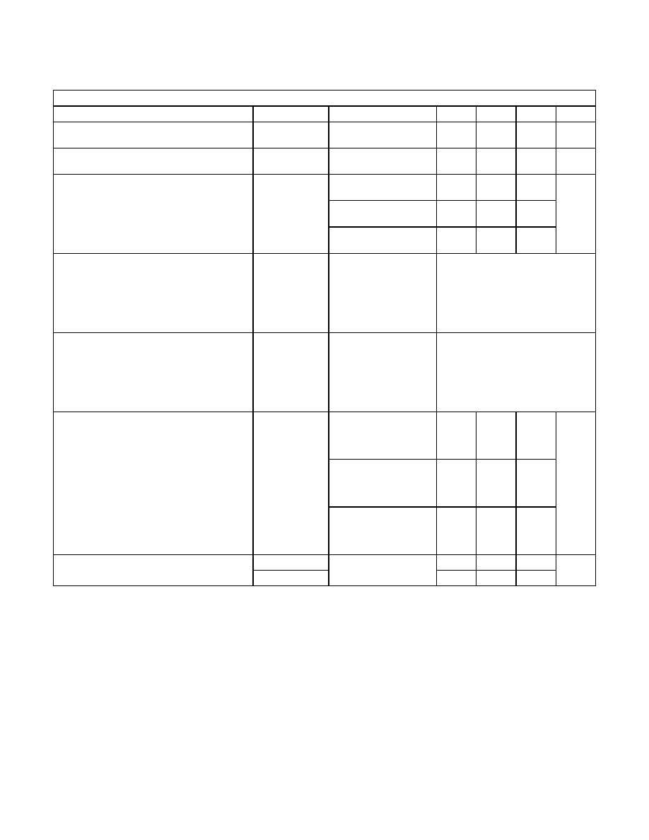
Table 3. CX77304-16 Electrical Specifications
(1)
(3 of 6)
DCS1800 Mode (f = 1710 to 1785 MHz and P
IN
= 6 to 11 dBm)
Parameter Symbol
Test
Condition
Minimum
Typical
Maximum
Units
Frequency range
f
--
1710
--
1785
MHz
Input power
P
IN
--
6
--
11
dBm
Analog power control voltage
V
APC
P
OUT
= 29.5 dBm
1.35
1.7
2.1
V
Leakage current
I
Q
V
CC
= 4.5 V
V
APC
= 0.3 V
T
CASE
= +25
°C
No RF input
-- -- 5 µA
PAE
V
CC
= 3.5 V
P
OUT
32 dBm
V
APC
2.0 V
pulse width 577 µs
duty cycle 1:8
T
CASE
= +25
°C
42 45 --
Power Added Efficiency
PAE
_LOW INPUT
V
CC
= 3.5 V
P
OUT
32 dBm
V
APC
2.0 V
pulse width 577 µs
duty cycle 1:8
T
CASE
= +25
°C
P
IN
= 4 dBm
-- 49 --
%
2nd and 3rd 2f
0
, 3f
0
BW = 3 MHz
5 dBm
P
OUT
32 dBm
V
CC
= 3.5 V
T
CASE
= +25 °C
-- -- 0
Harmonics
4th to 7th
4f
0
to 7f
0
BW = 3 MHz
5 dBm
P
OUT
32 dBm
-- -- 7
dBm
P
OUT
V
CC
= 3.5 V
V
APC
2.0 V
T
CASE
= +25
°C
32.0 32.5 --
P
OUT_MAX LOW INPUT
V
CC
= 3.5 V
V
APC
2.0 V
T
CASE
= +25
°C
P
IN
= 4 dBm
-- 32.1 --
P
OUT_MAX LOW VOLTAGE
V
CC
= 2.9 V
V
APC
2.6 V
T
CASE
= 20
°C to +100 °C
(See Table 2 for multislot)
P
IN
= 6 dBm
29.5 30.5 --
Output power
P
OUT_MAX HIGH VOLTAGE
V
CC
= 4.8 V
V
APC
2.6 V
T
CASE
= 20
°C to +100 °C
(See Table 2 for multislot)
P
IN
= 6 dBm
29.5 30.5 --
dBm