 | –≠–ª–µ–∫—Ç—Ä–æ–Ω–Ω—ã–π –∫–æ–º–ø–æ–Ω–µ–Ω—Ç: GMV9801 | –°–∫–∞—á–∞—Ç—å:  PDF PDF  ZIP ZIP |
Skyworks Solutions, Inc. [781] 376-3000
∑ Fax [781] 376-3100 ∑ Email sales@skyworksinc.com ∑ www.skyworksinc.com
1
Specifications subject to change without notice. 5/03A
GaAs Hyperabrupt Junction
Varactor Diodes
Features
Constant Gamma of 1.0 and 1.25
Highly Linear Frequency Tuning
Constant Modulation Sensitivity
Lower Series Resistance and Higher Q in
Comparison to Equivalent Silicon
Hyperabrupt Varactors
GMV7811, GMV7821
GMV9801, GMV9821, GMV9822
Description
This series of GaAs hyperabrupt varactor diodes features
a constant gamma of 1.0 and 1.25, which allows for a
relatively linear frequency tuning for VCOs, modulators and
tunable filters. Varactors in this series are grown by MBE
(Molecular Beam Epitaxy), which allows monolayer
control of the doping profile.This translates to superb wafer-
to-wafer uniformity. The series resistance is lower, and Q
is higher when compared to an equivalent silicon
hyperabrupt varactor. These diodes are suited for
applications at X band frequencies and above, where wide
change in frequency is desired. However, in certain
applications the GaAs hyperabrupt varactor exhibits a
higher surface noise in comparison to an equivalent silicon
varactor.
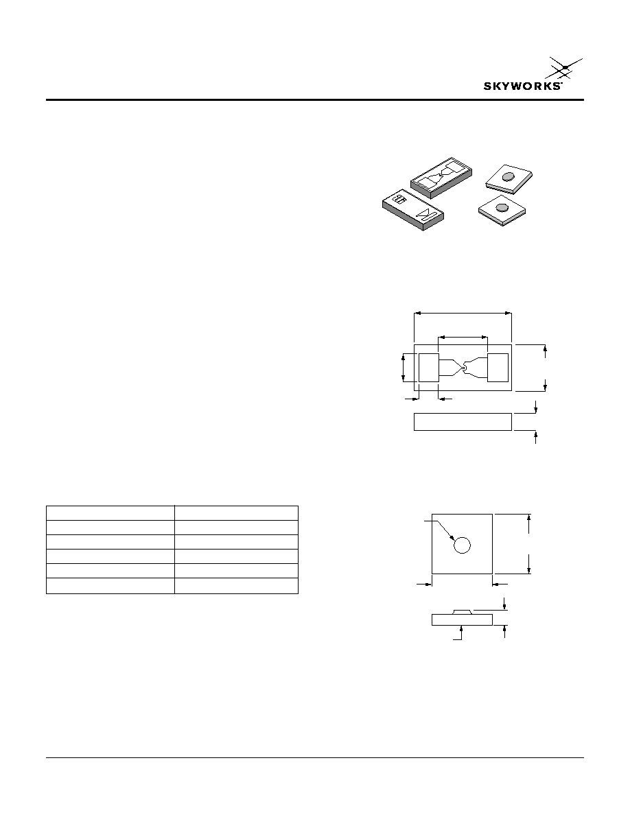
0.026 (0.66 mm)
± 0.001 (0.025 mm)
0.013 (0.33 mm)
± 0.001 (0.025 mm)
0.005 (0.13 mm)
± 0.001 (0.025 mm)
0.013 (0.33 mm)
± 0.001 (0.025 mm)
0.004 (0.10 mm)
± 0.001 (0.025 mm)
MAX.
0.008 (0.20 mm)
± 0.001 (0.025 mm)
Outline Drawings
540-011
METALLIZED BACK
CONTACT GOLD
0.010 (0.25 mm)
± 0.001 (0.025 mm)
METALLIZED GOLD DOT
0.0011 (0.0279 mm)
MIN. DIA.
0.010 (0.25 mm)
± 0.001 (0.025 mm)
0.005 (0.13 mm) NOM.
150-808
Flip Chip
Chip
Characteristic
Value
Reverse Voltage (V
R
)
18 V
Forward Current (I
F
)
100 mA
Power Dissipation at 25∞C
250 mW
Operating Temperature (T
OP
)
-55∞C to +150∞C
Storage Temperature (T
ST
)
-65∞C to +200∞C
Absolute Maximum Ratings
GaAs Hyperabrupt Junction Varactor Diodes
2
Skyworks Solutions, Inc. [781] 376-3000
∑ Fax [781] 376-3100 ∑ Email sales@skyworksinc.com ∑ www.skyworksinc.com
Specifications subject to change without notice. 5/03A
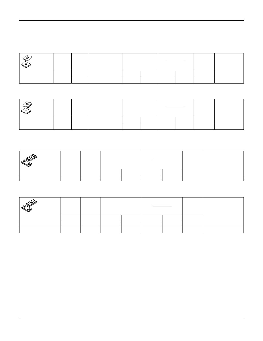
GMV7811, GMV7821, GMV9801, GMV9821, GMV9822
Junction
V
B
I
R
Capacitance
C
J
@ 2 V
Outline
Part
@ 10
µ
µA @ 14.4 V
C
J
@ 4 V
C
J
@ 12 V
Q @ 4 V
Drawing
Number
(V)
(nA)
(pF)
(Ratio)
50 MHz
Number
Min.
Max.
Min.
Max.
Min.
Max.
Typ.
GMV7811-000 18 100
2≠12
0.4
0.6
3.63
4.43
4000 150-808
Junction
V
B
I
R
Capacitance
C
J
@ 2 V
Outline
Part
@ 10
µ
µA
@ 14.4 V
C
J
@ 4 V
C
J
@ 12 V
Q @ 4 V
Drawing
Number
(V)
(nA)
(pF)
(Ratio)
50 MHz
Number
Min.
Max.
Min.
Max.
Min.
Max.
Typ.
GMV7821-000 18
100
0.4
0.6
3.30
4.10
4000 540-011
GaAs Hyperabrupt Junction Varactor Chips
Gamma = 1.0
Electrical Characteristics
GaAs Hyperabrupt Junction Varactor Flip Chips
Gamma = 1.0
V
B
I
R
Junction
C
J
@ 2 V
Outline
Part
@ 10
µ
µA @ 14.4 V
Capacitance
C
J
@ 12 V
Q @ 4 V
Drawing
Number
(V)
(nA)
(pF)
(Ratio)
50 MHz
Number
Min.
Max.
Min.
Max.
Min.
Max.
Typ.
GMV9801-000 18 100
2≠12
0.3 0.4 5.14
6.28
4000 150-808
Junction
V
B
I
R
Capacitance
C
J
@ 2 V
Outline
Part
@ 10
µ
µA
@ 14.4 V
C
J
@ 4 V
C
J
@ 12 V
Q @ 4 V
Drawing
Number
(V)
(nA)
(pF)
(Ratio)
50 MHz
Number
Min.
Max.
Min.
Max.
Min.
Max.
Typ.
GMV9821-000 18 100
0.3 0.4
4.30
5.27
4000
540-011
GMV9822-000 18 100
0.4 0.6
4.53
5.55
3500
540-011
Gamma = 1.25
Available through distribution.
Gamma = 1.25
Typical Voltage
Range of Gamma
(V)
Typical Voltage
Range of Gamma
(V)

GaAs Hyperabrupt Junction Varactor Diodes
Skyworks Solutions, Inc. [781] 376-3000
∑ Fax [781] 376-3100 ∑ Email sales@skyworksinc.com ∑ www.skyworksinc.com
3
Specifications subject to change without notice. 5/03A
GMV7811, GMV7821, GMV9801, GMV9821, GMV9822
Part
C
J0
V
J
M
C
P
Number
(pF)
(V)
(pF)
GMV7811
1.38
5.20
2.10
0.080
GMV9801
1.12
5.50
2.30
0.030
GMV7821
1.33
5.20
2.00
0.080
GMV9821
1.07
5.50
2.40
0.060
GMV9822
1.55
5.50
2.40
0.080
Typical Capacitance Values
SPICE Model
GMV7811
GMV9801 GMV7821
GMV9821 GMV9822
V
R
(V)
C
J
(pF)
C
J
(pF)
C
J
(pF)
C
J
(pF)
C
J
(pF)
0
1.38
1.12
1.33
1.07
1.55
1
1.03
0.84
1.01
0.81
1.17
2
0.80
0.63
0.79
0.61
0.88
3
0.62
0.45
0.61
0.45
0.64
4
0.50
0.35
0.50
0.35
0.50
5
0.42
0.28
0.42
0.29
0.41
6
0.36
0.23
0.37
0.24
0.34
7
0.32
0.20
0.33
0.21
0.30
8
0.28
0.17
0.30
0.19
0.26
9
0.26
0.15
0.27
0.17
0.23
10
0.23
0.14
0.25
0.15
0.21
11
0.22
0.12
0.23
0.14
0.19
12
0.20
0.11
0.21
0.13
0.18
1. Values extracted from measured performance.
DIODE
Varactor_Diode
AREA = 1
MODEL = Diode_Model
MODE = nonlinear
RES
R
S
R = R
S
CAP
C
P
C = C
P
PORT
P_anode
port = 1
PORT
P_Cathode
port = 2
DIODEM
Diode_Model
I
S
= 1.00e-14
0.5e-12
R
S
= 0
N = 1
T
T
= 0
C
JO
= C
JO
M = M
V
J
= V
J
E
G
= 1.11
1.43
X
TI
= 3
2
K
F
=0
A
F
=1
F
C
= 0.5
B
V
= 0
I
BV
= 1e-3
I
SR
= 0
N
R
= 2
I
KF
= 0
N
BV
= 1
I
BVL
= 0
N
BVL
= 1
T
BV1
= 0
T
NOM
= 27
F
FE
= 1
C
V
=
+ C
P
1+
C
J0
M
V
R
V
J