 | –≠–ª–µ–∫—Ç—Ä–æ–Ω–Ω—ã–π –∫–æ–º–ø–æ–Ω–µ–Ω—Ç: SMV1419 | –°–∫–∞—á–∞—Ç—å:  PDF PDF  ZIP ZIP |
Characteristic
Value
Reverse Voltage (V
R
)
30 V
Forward Current (I
F
)
20 mA
Power Dissipation (P
D
)
250 mW
Storage Temperature (T
ST
)
-55∞C to +150∞C
Operating Temperature (T
OP
)
-55∞C to +125∞C
Absolute Maximum Ratings
Skyworks Solutions, Inc. [978] 241-7000
∑ Fax [978] 241-7906 ∑ Email sales@skyworksinc.com ∑ www.skyworksinc.com
1
Specifications subject to change without notice. 12/02A
Abrupt Junction Tuning Varactors
Features
High Q
Low Series Resistance for Low Phase
Noise
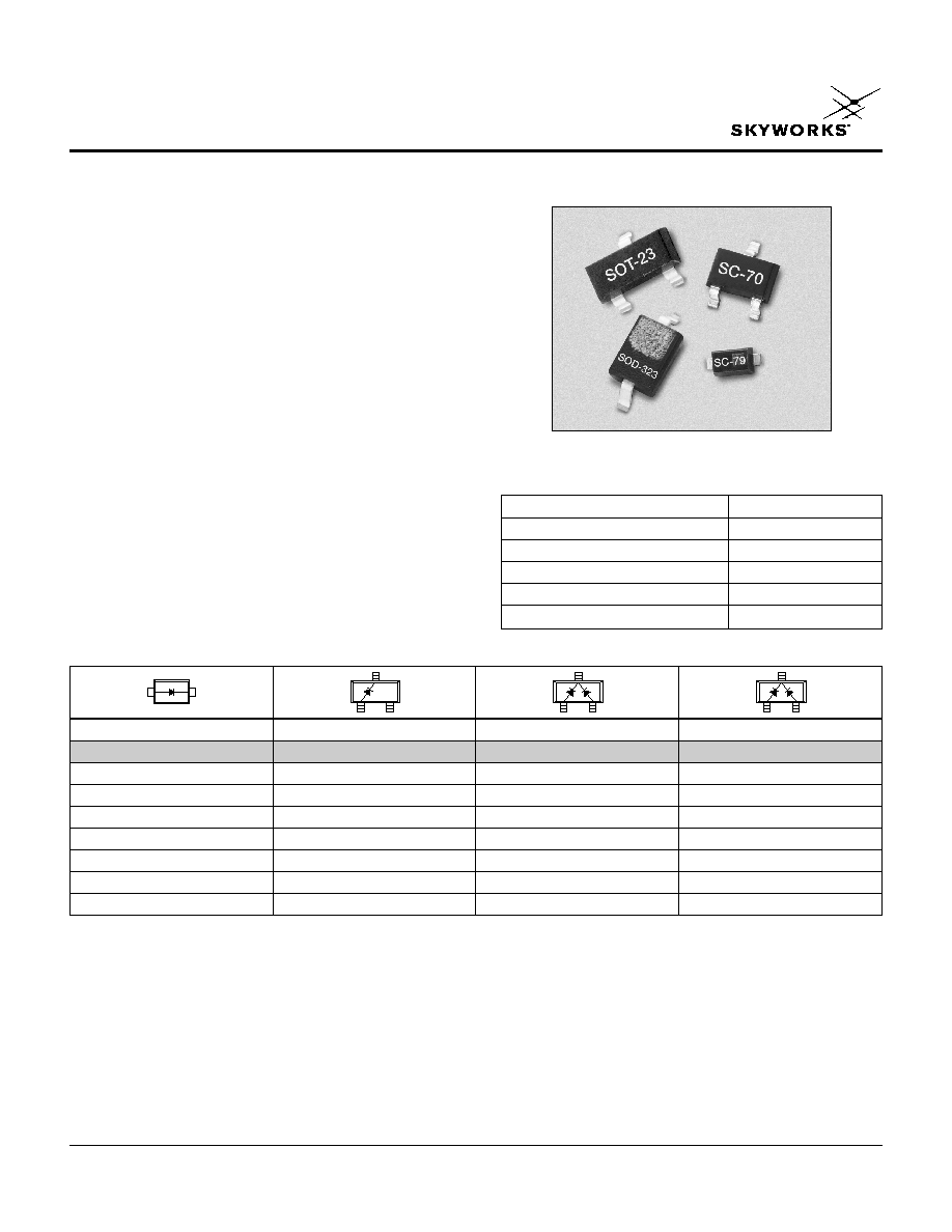
Multiple Packages SOT-23, SOD-323,
SC-70 and SC-79
Designed for High Volume Commercial
Applications
SPICE Models are Available
SMV1405≠SMV1419
Description
The SMV1405≠SMV1419 series of silicon abrupt junction
varactor diodes are designed for use in VCOs requiring tight
capacitance tolerances. The low resistance of these
varactors makes them appropriate for high Q resonators
in wireless system VCOs to frequencies beyond 2.5 GHz.
The devices are characterized for capacitance over
temperature. SPICE models are provided.
Single
Single
Common Cathode
Common Cathode
SC-79
SOT-23
SOT-23
SC-70
SMV1405-079
SMV1405-001
SMV1405-074
SMV1408-001
SMV1413-001
SMV1417-001
SMV1417-004
SMV1419-001
L
S
= 0.7 nH
L
S
= 1.5 nH
L
S
= 1.5 nH
L
S
= 1.4 nH
Available through distribution.
For other packages or configurations, please contact the factory.

Abrupt Junction Tuning Varactors
SMV1405≠SMV1419
2
Skyworks Solutions, Inc. [978] 241-7000
∑ Fax [978] 241-7906 ∑ Email sales@skyworksinc.com ∑ www.skyworksinc.com
Specifications subject to change without notice. 12/02A
0.1
1.0
10.0
100.0
Reverse Voltage (V)
Capacitance vs. Reverse Voltage
Capacitance (pF)
0
5
10
15
20
25
30
SMV1419
SMV1417
SMV1413
SMV1408
SMV1405
-5
-4
-3
-1
-2
0
1
2
3
5
4
6
-40
-20
0
20
40
60
80
Percentage Change (%)
Temperature (∞C)
Relative Capacitance Change
vs. Temperature
V
R
= 1 V
V
R
= 4 V
V
R
= 30 V
Typical Performance Data
Typical Capacitance Values
SMV1405
SMV1408
SMV1413
SMV1417
SMV1419
V
R
(V)
C
T
(pF)
C
T
(pF)
C
T
(pF)
C
T
(pF)
C
T
(pF)
0.0
2.67
4.08
9.24
19.20
23.44
0.5
2.12
3.36
7.39
15.30
18.72
1.0
1.84
2.94
6.37
13.16
16.64
1.5
1.70
2.60
5.71
11.76
14.38
2.0
1.55
2.38
5.22
10.74
13.14
2.5
1.44
2.24
4.85
9.95
12.18
3.0
1.34
2.08
4.55
9.32
11.42
4.0
1.25
1.88
4.10
8.35
10.26
5.0
1.17
1.72
3.77
7.64
9.40
10.0
0.95
1.28
2.85
5.62
7.00
20.0
0.77
1.01
2.12
4.09
5.10
30.0
0.63
0.95
1.77
3.79
4.30
C
T
C
T
C
T
@ 0 V
R
S
@ 4 V
Q
Part
@ 0.5 V
@ 1 V
C
T
@ 4 V
C
T
@ 30 V
500 MHz
@ 4 V
Number
(pF)
(pF)
(pF)
(Ratio)
(
)
50 MHz
Typ.
Typ.
Min.
Max.
Min.
Max.
Typ.
SMV1405
2.1
1.8
1.21
1.45
4.1
0.80
3200
SMV1408
3.4
2.9
1.75
2.11
4.1
0.60
2900
SMV1413
7.4
6.4
3.64
4.42
4.2
0.35
2400
SMV1417
15.3
13.2
7.51
9.15
4.3
0.22
1800
SMV1419
18.7
16.6
9.13
11.13
4.4
0.20
1600
Electrical Specifications at 25∞C
Reverse Voltage V
R
(I
R
= 10
µA): 30 V
Reverse Current I
R
(V
R
= 24 V): 20 nA

Abrupt Junction Tuning Varactors
SMV1405≠SMV1419
Skyworks Solutions, Inc. [978] 241-7000
∑ Fax [978] 241-7906 ∑ Email sales@skyworksinc.com ∑ www.skyworksinc.com
3
Specifications subject to change without notice. 12/02A
Part
C
JO
V
J
M
C
P
R
S
Number
(pF)
(V)
(pF)
(
)
SMV1405
2.92
0.68
0.41
0.05
0.80
SMV1408
3.70
0.80
0.48
0.13
0.60
SMV1413
9.20
0.79
0.45
0.13
0.35
SMV1417
19.20
0.84
0.48
0.13
0.22
SMV1419
23.40
0.87
0.54
0.13
0.20
SPICE Model
1. Values extracted from measured performance.
2. For package inductance (L
S
) refer to package type.
3. For more details refer to the "Varactor SPICE Models for RF VCO
Applications" Application Note.
DIODE
Varactor_Diode
AREA = 1
MODEL = Diode_Model
MODE = nonlinear
RES
R
S
R = R
S
IND
L
S
L = L
S
CAP
C
P
C = C
P
PORT
P_anode
port = 1
PORT
P_Cathode
port = 2
DIODEM
Diode_Model
I
S
= 1.00e-14
R
S
= 0
N = 1
T
T
= 0
C
JO
= C
JO
M = M
V
J
= V
J
E
G
= 1.11
X
TI
= 3
K
F
=0
A
F
=1
F
C
= 0.5
B
V
= 0
I
BV
= 1e-3
I
SR
= 0
N
R
= 2
I
KF
= 0
N
BV
= 1
I
BVL
= 0
N
BVL
= 1
T
BV1
= 0
T
NOM
= 27
F
FE
= 1
SOT-23
3
2
1
0.035 (0.89 mm) MIN.
0.044 (1.12 mm) MAX.
0.0005 (0.01 mm) MIN.
0.004 (0.10 mm) MAX.
0.012 (0.30 mm) MIN.
0.020 (0.50 mm) MAX.
0.003 (0.080 mm) MIN.
0.008 (0.20 mm) MAX.
8∞ MAX.
0.022 (0.55 mm) REF.
0.110 (2.80 mm) MIN.
0.120 (3.04 mm) MAX.
0.083 (2.10 mm) MIN.
0.104 (2.64 mm) MAX.
0.037 (0.95 mm) REF.
0.047 (1.20 mm) MIN.
0.055 (1.40 mm) MAX.
0.076 (1.92 mm) REF.
0.020 (0.51 mm) REF.
SC-70
3
2
1
0.031 (0.80 mm) MIN.
0.039 (1.00 mm) MAX.
0.000 (0.00 mm) MIN.
0.004 (0.10 mm) MAX.
0.010 (0.25 mm) MIN.
0.016 (0.40 mm) MAX.
0.071 (1.80 mm) MIN.
0.087 (2.20 mm) MAX.
0.071 (1.80 mm) MIN.
0.094 (2.40 mm) MAX.
0.045 (1.15 mm) MIN.
0.053 (1.35 mm) MAX.
0.026 (0.65 mm) REF.
0.051 (1.30 mm) REF.
0.004 (0.10 mm) MIN.
0.007 (0.18 mm) MAX.
0.004 (0.10 mm) MIN.
0.012 (0.30 mm) MAX.
0.014 (0.35 mm) REF.
SOD-323
0.090 (2.30 mm) MIN.
0.108 (2.74 mm) MAX.
0.045 (1.15 mm) MIN.
0.053 (1.35 mm) MAX.
0.050
(1.25 mm) MAX.
0.006
(0.15 mm) TYP.
0.008 (0.20 mm) NOM.
0.004 (0.10 mm) MAX.
0.010 (0.25 mm) MIN.
0.010
(0.25 mm) MIN.
0.016
(0.40 mm) MAX.
0.063 (1.60 mm) MIN.
0.071 (1.80 mm) MAX.
CATHODE
INDICATOR
2
1
SC-79
0.060 (1.50 mm) MIN.
0.067 (1.70 mm) MAX.
0.010
(0.25 mm) MIN.
0.014
(0.35 mm) MAX.
0.043 (1.10 mm) MIN.
0.051 (1.30 mm) MAX.
0.020
(0.50 mm) MIN.
0.028
(0.70 mm) MAX.
0.003
(0.07 mm) MIN.
0.008
(0.20 mm) MAX.
10∞ MAX.
10∞ MAX.
0.028
(0.70 mm) MIN.
0.035
(0.90 mm) MAX.
0.006 (0.15 mm) MIN.
CATHODE
INDICATOR
1
2