 | –≠–ª–µ–∫—Ç—Ä–æ–Ω–Ω—ã–π –∫–æ–º–ø–æ–Ω–µ–Ω—Ç: 20H04 | –°–∫–∞—á–∞—Ç—å:  PDF PDF  ZIP ZIP |
SMSC USB20H04
Page 1
Revision 1.63 (10-14-04)
DATASHEET
USB20H04
4-Port USB2.0 Hub
Controller
Datasheet
Product Features
General Features
Compliant with USB2.0 Specification
Hub controller IC with four downstream ports
Four transaction translators ensure maximum USB
throughput
Enables bus-powered Hi-Speed hub design
Compatible with On-The-Go (OTG) USB devices
Integrated Session Request Protocol (SRP)
operates with dual-role OTG hosts
Default configuration with pin selectable options
Serial interface for configuration from EEPROM or
microcontroller when default is not used
Flexible OEM configuration options
Available in a 64-pin TQFP package
Hardware Features
Detects removal of self-power and automatically
changes mode to bus-power
Integrated
termination and pull-up/pull-down
resistors
Internal short circuit protection of DP and DM lines
On-chip oscillator uses low cost 24MHz crystal
Supports individual or ganged over-current
protection and power control
LED drivers for each downstream port
OEM Selectable Features
Configure as a bus-powered or self-powered
Hi-Speed USB hub
Configure port power switching and current
sensing on an individual or ganged basis
Enable LED indicator support
Enable multiple transaction translators
Enable compound device support on a port by port
basis
Enable downstream facing ports on a port by port
basis
Pin Selectable Options for Default Configuration
Select operation as either a Bus-Powered hub or a
Self-Powered hub
ORDERING INFORMATION
Order Number(s):
USB20H04-JD for 64 pin, 10x10x1.4 TQFP package
USB20H04-JT for 64 pin, 10x10x1.4 TQFP package (green, lead-free)

4-Port USB2.0 Hub Controller
Datasheet
Revision 1.63 (10-14-04)
Page 2
SMSC USB20H04
DATASHEET
80 Arkay Drive
Hauppauge, NY 11788
(631)
435-6000
FAX (631) 273-3123
Copyright © SMSC 2004. All rights reserved.
Circuit diagrams and other information relating to SMSC products are included as a means of illustrating typical applications. Consequently, complete
information sufficient for construction purposes is not necessarily given. Although the information has been checked and is believed to be accurate, no
responsibility is assumed for inaccuracies. SMSC reserves the right to make changes to specifications and product descriptions at any time without
notice. Contact your local SMSC sales office to obtain the latest specifications before placing your product order. The provision of this information
does not convey to the purchaser of the described semiconductor devices any licenses under any patent rights or other intellectual property rights of
SMSC or others. All sales are expressly conditional on your agreement to the terms and conditions of the most recently dated version of SMSC's
standard Terms of Sale Agreement dated before the date of your order (the "Terms of Sale Agreement"). The product may contain design defects or
errors known as anomalies which may cause the product's functions to deviate from published specifications. Anomaly sheets are available upon
request. SMSC products are not designed, intended, authorized or warranted for use in any life support or other application where product failure
could cause or contribute to personal injury or severe property damage. Any and all such uses without prior written approval of an Officer of SMSC
and further testing and/or modification will be fully at the risk of the customer. Copies of this document or other SMSC literature, as well as the Terms
of Sale Agreement, may be obtained by visiting SMSC's website at http://www.smsc.com. SMSC is a registered trademark of Standard Microsystems
Corporation ("SMSC"). Product names and company names are the trademarks of their respective holders.
SMSC DISCLAIMS AND EXCLUDES ANY AND ALL WARRANTIES, INCLUDING WITHOUT LIMITATION ANY AND ALL IMPLIED WARRANTIES
OF MERCHANTABILITY, FITNESS FOR A PARTICULAR PURPOSE, TITLE, AND AGAINST INFRINGEMENT AND THE LIKE, AND ANY AND
ALL WARRANTIES ARISING FROM ANY COURSE OF DEALING OR USAGE OF TRADE.
IN NO EVENT SHALL SMSC BE LIABLE FOR ANY DIRECT, INCIDENTAL, INDIRECT, SPECIAL, PUNITIVE, OR CONSEQUENTIAL DAMAGES;
OR FOR LOST DATA, PROFITS, SAVINGS OR REVENUES OF ANY KIND; REGARDLESS OF THE FORM OF ACTION, WHETHER BASED ON
CONTRACT; TORT; NEGLIGENCE OF SMSC OR OTHERS; STRICT LIABILITY; BREACH OF WARRANTY; OR OTHERWISE; WHETHER OR
NOT ANY REMEDY OF BUYER IS HELD TO HAVE FAILED OF ITS ESSENTIAL PURPOSE, AND WHETHER OR NOT SMSC HAS BEEN
ADVISED OF THE POSSIBILITY OF SUCH DAMAGES.
4-Port USB2.0 Controller
Datasheet
SMSC USB20H04
Page 3
Revision 1.63 (10-14-04)
DATASHEET
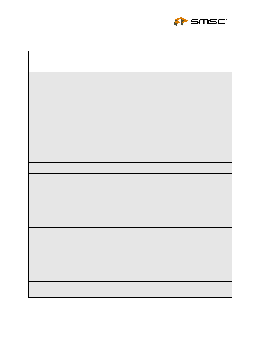
USB20H04 Datasheet Revisions
PAGE(S) SECTION/FIGURE/ENTRY
CORRECTION
REVISION LEVEL
AND DATE
Cover
Ordering Information
Added lead-free part number
Revision 1.63
(10-14-04)
26
Table 8.4
Removed 0000 from the over-current timer
value, which places it into the reserved
category
Revision 1.62
(09-10-04)
15, 16,
18
Table 5.2, 6.1, 6.2, 6.4
Lower limit for the 1.8V regulator
specification changed from 1.6 to 1.74V.
(Note upper limit restored to previous value
of 2.0V)
Revision 1.61
(07-28-04)
15
Table 5.2 ≠ Recommended
Operating Conditions
1.8V regulator specification changed to
±5%. (was ±10%)
Revision 1.6
(07-14-04)
13
Table 4.3 - USB I/O Signals
VBUSDET pin description updated
Revision 1.5
(04-01-04)
Cover
Title
Title changed from "Hi-Speed USB Hub
Controller IC" to "4-Port USB2.0 Hub
Controller"
Revision 1.4
(12-10-03)
24
Figure 8.2 - Internal Default Mode
Updated diagram.
Revision 1.3
11-13-03
20
7.5.2 - I
2
C Memory Interface
Removed last sentence.
Revision 1.3
11-11-03
24
Figure 8.2 - Internal Default Mode
Updated figure.
Revision 1.3
11-11-03
27
Table 8.6 - Default Configuration
Values
Updated table with note about PID
changing with silicon revision.
Revision 1.3
11-11-03
36
Figure 10.1 - High Level Block
Diagram of a Self-Powered Hub
Removed (128x8) from figure.
Revision 1.3
11-11-03
Cover - Ordering Information
Changed from "USB20H04L-JD" to
"USB20H04-JD".
Revision 1.3
11-05-03
8
Chapter 1 General Description
Added paragraph 3.
Revision 1.3
10-31-03
9
1.3 Pin Selectable Options to the
Default Configuration
Added new section.
Revision 1.3
10-31-03
10
Figure 2.1 - Block Diagram
Added default configuration to diagram.
Revision 1.3
10-31-03
19
7.4 Internal Configuration Select
Section is updated.
Revision 1.3
10-31-03
24
8.1.2 Internal Default Configuration
Section is updated.
Revision 1.3
10-31-03
27
Table 8.6 - Default Configuration
Values
Table added.
Revision 1.3
10-31-03
23
Chapter 8 Implementation Notes
Modified first paragraph.
Revision 1.2
08-04-03
28
Table 8.7 - Time Values to
Configure from SMBus
Values added to MAX column:
T2 ≠ 32 ns
T4 ≠ 70 ns
Revision 1.2
08-04-03
4-Port USB2.0 Hub Controller
Datasheet
Revision 1.63 (10-14-04)
Page 4
SMSC USB20H04
DATASHEET
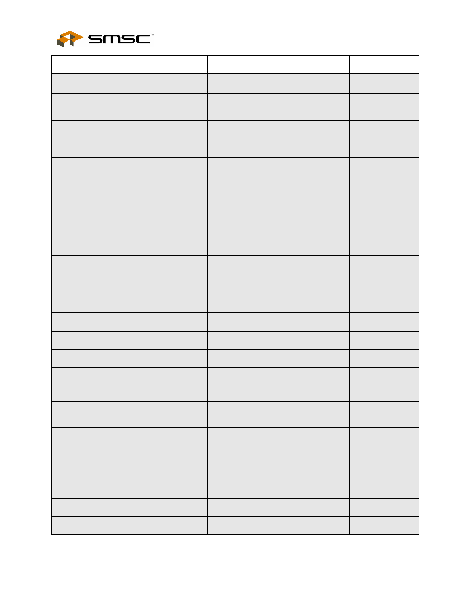
PAGE(S) SECTION/FIGURE/ENTRY
CORRECTION
REVISION LEVEL
AND DATE
29
Table 8.8 - Time Values to
Configure From EEPROM
Value added to MAX column:
T4 ≠ 70 ns
Revision 1.2
08-04-03
28
Figure 8.3 - Timing for
Configuration from SMBus
Updated figure
Revision 1.2
08-04-03
29
Figure 8.4 - Timing to Complete
Configuration from EEPROM
Updated figure
Revision 1.2
08-04-03
16, 16,
18
Chapter 6 Electrical Characteristics
Updated the following tables:
Table 6.1 - Electrical Characteristics:
Supply Pins, Table 6.2 - DC Electrical
Characteristics: Digital Pins, Table 6.4 - DC
Electrical Characteristics: Analog I/O Pins
(DP/DM)
Removed Table 6.5 ≠ Dynamic
Characteristics: Analog I/O Pins (DP/DM)
Revision 1.2
07-31-03
27
8.4.1 External Hardware Reset
Updated section
Revision 1.2
07-31-03
28
Table 8.7 - Time Values to
Configure from SMBus
Updated table
Revision 1.2
07-31-03
29
8.4.1.2 EEPROM Configuration
Timing
Updated:
Table 8.8 - Time Values to Configure From
EEPROM
Revision 1.2
07-31-03
Features
Changed reference to QFP package to
TQFP package.
Revision 1.1
07/28/03
11
Figure 3.1≠ 64 Pin TQFP
Updated figure title
Revision 0.94
1/31/03
13
Table 4.3 - USB I/O Signals
See tracked changes
Revision 0.94
1/31/03
15
Table 5.1 - Absolute Maximum
Ratings (In accordance with the
Absolute Maximum Rating system
(IEC 60134)
Replaced table
Revision 0.94
1/31/03
18
Table 6.4 - DC Electrical
Characteristics: Analog I/O Pins
(DP/DM)
Removed reference to Figure 6.1
Revision 0.94
1/31/03
18
Dynamic Characteristics: Analog
I/O Pins (DP/DM)
Removed references to Figure 6.2
Revision 0.94
1/31/03
19
7.1 Bus-Power Detect
See tracked changes
Revision 0.94
1/31/03
20
7.5.1 SMBus Slave
See tracked changes
Revision 0.94
1/31/03
23
8.1 Configuration Implementations
See tracked changes
Revision 0.94
1/31/03
23
8.1.1 Interfacing a 2-wire Serial
EEPROM
See tracked changes
Revision 0.94
1/31/03
24
Table 8.1 - Summary of OEM
Value Programming
See tracked changes
Revision 0.94
1/31/03
4-Port USB2.0 Controller
Datasheet
SMSC USB20H04
Page 5
Revision 1.63 (10-14-04)
DATASHEET
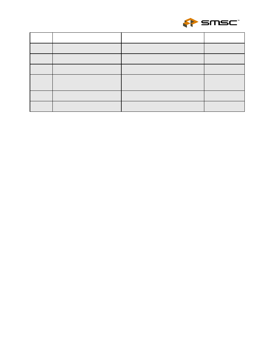
PAGE(S) SECTION/FIGURE/ENTRY
CORRECTION
REVISION LEVEL
AND DATE
25
Table 8.3 - Address 7;
Config_Byte_2
See tracked changes
Revision 0.94
1/31/03
-
Figure 8.3 ≠ RESET_N Timing for
EEPROM Mode
This figure has been removed
Revision 0.94
1/31/03
-
Table 8.6 ≠ RESET_N Timing for
EEPROM Mode
This table has been removed
Revision 0.94
1/31/03
28
Figure 8.3 - Timing for
Configuration from SMBus
Added figure
Revision 0.94
1/31/03
28
Table 8.7 - Time Values to
Configure from SMBus
Added table
Revision 0.94
1/31/03
36
Figure 10.1 - High Level Block
Diagram of a Self-Powered Hub
Updated figure
Revision 0.94
1/31/03