 | –≠–ª–µ–∫—Ç—Ä–æ–Ω–Ω—ã–π –∫–æ–º–ø–æ–Ω–µ–Ω—Ç: 34C60 | –°–∫–∞—á–∞—Ç—å:  PDF PDF  ZIP ZIP |

SMSC DS ≠ PPC34C60
Rev. 06/01/2001
ADVANCED INFORMATION
Parallel Port Interface Chip - Peripheral Side
FEATURES
Creates PC/AT-Style Bus from Parallel Printer Port
Signals
Single Chip Interface to Any Bus Capable Peripheral
Supports Standard, Bi-Directional, EPP, and ECP
Parallel Ports
Burst Mode for Improved Data Transfer Rates
Adaptive Interface Optimizes Transfer Rates to
Parallel Port Characteristics
Digital Signal Filtering Increases Noise Immunity
Allows Daisy-Chain of up to Eight Peripherals
Including Standard Printer
Provides Interrupt Sharing with Daisy-Chained
Devices
16-Bit Product ID Support
Peripheral Bus Clock Selectable at System Clock /2,
/3, /5, or /6
Interfaces to 8-Bit and/or 16-Bit Peripherals
FIFO Operation Permits Overlapping Parallel Port and
Peripheral Bus Cycles for Maximum Data Transfer
Rate
Flexible DRAM Buffer Support and DMA Capability
Four Output Lines Individually Configurable as Chip
Selects or General Purpose Outputs
Three Output Lines Individually Configurable as
Strobes or General Purpose Outputs
Four Uncommitted Inputs
Watchdog Monitors Host Computer Activity
Low Battery Detect Input
Direct Output for Piezo Transducer
Support for Automatic Power Up/Down
Prevents Host System Latchup with Powerback
Control
On Chip Crystal Oscillator
GENERAL DESCRIPTION
The PPC34C60 provides a means of re-generating an IBM AT style (ISA) bus from the PC printer port signals. In addition
to Standard (Compatible) printer ports, the PPC34C60 supports PS/2 (bi-directional), EPP, and ECP ports. Up to eight
peripherals may be daisy chained between the computer and the printer. Printer operation is unaffected.
The PPC34C60 performs as an intelligent data mux. It multiplexes the printer port signals between the daisy chain
(pass-through) outputs and there-generated ISA bus. Furthermore, it handles breaking up 8- and 16-bit ISA data into 4- or
8-bit chunks for the parallel port.
The PPC34C60 also provides a piezo transducer driver for battery-powered systems. The transducer will signal low battery
with two repeated beeps. If the cable to the computer is disconnected, or if the host is dormant for about a minute, the
transducer will signal inactivity with four beeps. Additionally, a power-down signal can be provided to external circuitry to
automatically shut down system power during inactivity.
PPC34C60

SMSC DS ≠ PPC34C60
Page 2
Rev. 06/01/2001
ADVANCED INFORMATION
80 Arkay Drive
Hauppauge,
NY
11788
(631)
435-6000
FAX (631) 273-3123
Copyright © SMSC 2004. All rights reserved.
Circuit diagrams and other information relating to SMSC products are included as a means of illustrating typical applications. Consequently, complete
information sufficient for construction purposes is not necessarily given. Although the information has been checked and is believed to be accurate, no
responsibility is assumed for inaccuracies. SMSC reserves the right to make changes to specifications and product descriptions at any time without
notice. Contact your local SMSC sales office to obtain the latest specifications before placing your product order. The provision of this information does
not convey to the purchaser of the described semiconductor devices any licenses under any patent rights or other intellectual property rights of SMSC
or others. All sales are expressly conditional on your agreement to the terms and conditions of the most recently dated version of SMSC's standard
Terms of Sale Agreement dated before the date of your order (the "Terms of Sale Agreement"). The product may contain design defects or errors
known as anomalies which may cause the product's functions to deviate from published specifications. Anomaly sheets are available upon request.
SMSC products are not designed, intended, authorized or warranted for use in any life support or other application where product failure could cause
or contribute to personal injury or severe property damage. Any and all such uses without prior written approval of an Officer of SMSC and further
testing and/or modification will be fully at the risk of the customer. Copies of this document or other SMSC literature, as well as the Terms of Sale
Agreement, may be obtained by visiting SMSC's website at http://www.smsc.com. SMSC is a registered trademark of Standard Microsystems
Corporation ("SMSC"). Product names and company names are the trademarks of their respective holders.
SMSC DISCLAIMS AND EXCLUDES ANY AND ALL WARRANTIES, INCLUDING WITHOUT LIMITATION ANY AND ALL IMPLIED WARRANTIES
OF MERCHANTABILITY, FITNESS FOR A PARTICULAR PURPOSE, TITLE, AND AGAINST INFRINGEMENT AND THE LIKE, AND ANY AND
ALL WARRANTIES ARISING FROM ANY COURSE OF DEALING OR USAGE OF TRADE.
IN NO EVENT SHALL SMSC BE LIABLE FOR ANY DIRECT, INCIDENTAL, INDIRECT, SPECIAL, PUNITIVE, OR CONSEQUENTIAL DAMAGES;
OR FOR LOST DATA, PROFITS, SAVINGS OR REVENUES OF ANY KIND; REGARDLESS OF THE FORM OF ACTION, WHETHER BASED ON
CONTRACT; TORT; NEGLIGENCE OF SMSC OR OTHERS; STRICT LIABILITY; BREACH OF WARRANTY; OR OTHERWISE; WHETHER OR
NOT ANY REMEDY OF BUYER IS HELD TO HAVE FAILED OF ITS ESSENTIAL PURPOSE, AND WHETHER OR NOT SMSC HAS BEEN
ADVISED OF THE POSSIBILITY OF SUCH DAMAGES.

SMSC DS ≠ PPC34C60
Page 3
Rev. 06/01/2001
ADVANCED INFORMATION
TABLE OF CONTENTS
1 PIN
CONFIGURATION ..........................................................................................................................................4
1.1 Buffer
Type
Descriptions...........................................................................................................................11
1.2 General
Conventions .................................................................................................................................11
1.3 Reference
Documents ...............................................................................................................................11
2 PPC34C60
BLOCK DESCRIPTION ....................................................................................................................12
3 DAISY
CHAIN
COMMAND PROTOCOL.............................................................................................................13
3.1 Peripheral
System Design .........................................................................................................................14
3.2 Design
Example .........................................................................................................................................15
3.3 Device
Addressing.....................................................................................................................................16
3.4 Internal
Register Map.................................................................................................................................18
4 REGISTER
DESCRIPTIONS ...............................................................................................................................19
5 DRAM
BUFFER OPERATION.............................................................................................................................29
5.1 Dram
Physical Addressing........................................................................................................................30
6 SYSTEM
DATA
BUS CYCLES ...........................................................................................................................31
7 OPERATIONAL
DESCRIPTION..........................................................................................................................34
8 TIMING
DIAGRAMS ............................................................................................................................................36
8.1 DMA
Transfer Cycle Timing ......................................................................................................................57
SMSC DS ≠ PPC34C60
Page 4
Rev. 06/01/2001
ADVANCED INFORMATION
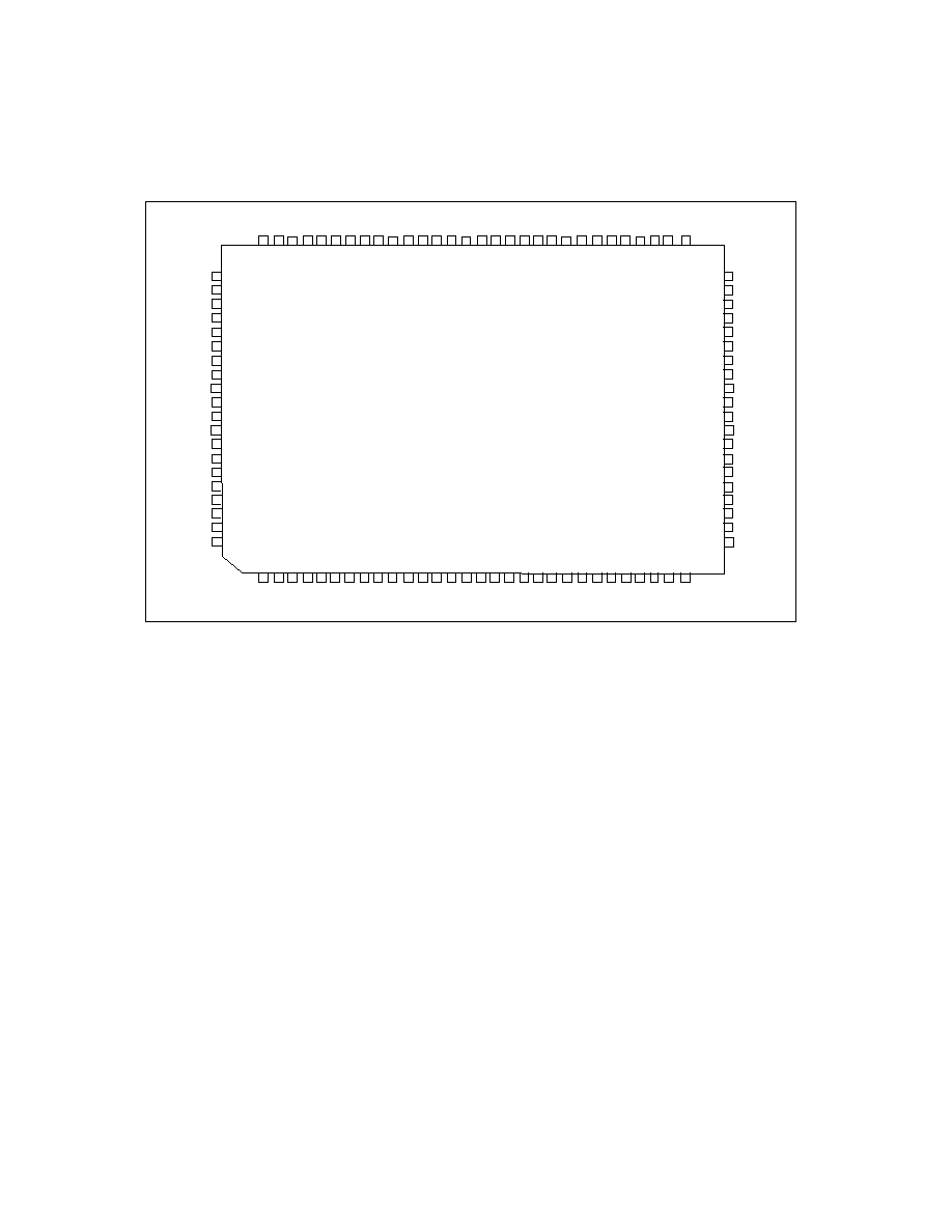
1 PIN
CONFIGURATION
50
49
48
47
46
45
44
43
42
41
40
39
38
37
36
35
34
33
32
31
81
82
83
84
85
86
87
88
89
90
91
92
93
94
95
96
97
98
99
100
nPID
SLCTD
IRQ
DREQ
TC
nDACK
nST0
nST1
nST2
VCC
GND
nWDOGEN
PIEZO
IN2
IN3
nLBAT
nRESET
SENSE
YIN
YOUT
nIO16
IN0
IN1
nCS0
nCS1
nCS2
nCS3
nSRD
nSWR
VCC
GND
nRAS
nCAS
nSRST
SRST
XIN(SCLK)
XOUT
BCLK
N/C
TEST
SD
0
SD
15
SD
14
SD
1
3
SD
1
2
SD
1
1
SD
10
SD
9
SD
8
GN
D
VC
C
SD
7
SD
6
SD
5
SD
4
SD
3
SD
2
SD
1
MA9
MA8
GND
VC
C
SA7
SA6
SA4
SA3
SA2
SA1
SA0
SA5
PPC34C60
30
29
28
27
26
25
24
23
22
21
20
19
18
17
16
15
14
13
12
11
10
9
8
7
6
5
4
3
2
1
HS
L
C
T
nPST
B
HP
E
nP
AL
F
H
BSY
n
PERR
nH
A
C
K
n
P
IN
IT
GND
VCC
HD7
HD
5
HD
4
HD
3
nH
SEL
HD2
nP
A
C
K
n
H
IN
IT
GN
D
VC
C
HD1
PBSY
HD
0
PPE
nH
ALF
nHS
T
B
nH
ER
R
PSLC
T
HD
6
nPSEL
51
52
53
54
55
56
57
58
59
60
61
62
63
64
65
66
67
68
69
70
71
72
73
74
75
76
77
78
79
80

SMSC DS ≠ PPC34C60
Page 5
Rev. 06/01/2001
ADVANCED INFORMATION
DESCRIPTION OF PIN FUNCTIONS
PIN NO.
NAME
SYMBOL
BUFFER
TYPE
DESCRIPTION
PARALLEL PORT HOST CONTROL AND COMMON DATA BUS INTERFACE
2 nHost:Strobe nHSTB
I,PU An active low pulse on this input is used
to strobe printer data into the printer.
Refer to Section 4 of the IEEE STD 1284
(Reference 1) for use of this pin in ECP
and EPP modes.
3
nHost:Auto Line
Feed
nHALF I,PU
This input goes low to cause the printer to
automatically feed one line after each line
is printed. Connects to AUTOFD output
from Host. Refer to Section 4 of the IEEE
STD 1284 (Reference 1) for use of this
pin in ECP and EPP modes.
14 nHost:SelectIn nHSEL
I This active low input is driven by the host
to select the printer. Connects to
SELECT IN output from Host. Refer to
Section 4 of the IEEE STD 1284
(Reference 1) for use of this pin in ECP
and EPP modes. (See Note 1 on Page
11.)
11 nHost:Initiate
nHINIT
I This active low input initiates the printer
when low. Connects to INIT output from
Host. Refer to Section 4 of the IEEE
STD 1284 (Reference 1) for use of this
pin in ECP and EPP modes. (See Note 1
on Page 11.)
24
nHost:
Acknowledge
nHACK O16
This active low output from the printer is
used to indicate that the printer has
received the data and is ready to accept
new data. Connects to the ACK input to
the Host. Refer to Section 4 of the IEEE
STD 1284 (Reference 1) for use of this
pin in ECP and EPP modes.
26 Host:Busy
HBSY
O16 This status output, generated by the
printer, goes high to indicate that it is not
ready to receive new data from the host.
Connects to the BUSY input to the Host.
Refer to Section 4 of the IEEE STD 1284
(Reference 1) for use of this pin in ECP
and EPP modes.
28 Host:Paper
End HPE
O16 This status output, generated by the
printer, goes high to indicate that the
printer is out of paper. Connects to the
PERROR input to the Host. Refer to
Section 4 of the IEEE STD 1284
(Reference 1) for use of this pin in ECP
and EPP modes.