 | –≠–ª–µ–∫—Ç—Ä–æ–Ω–Ω—ã–π –∫–æ–º–ø–æ–Ω–µ–Ω—Ç: SNC10B | –°–∫–∞—á–∞—Ç—å:  PDF PDF  ZIP ZIP |
SNC10B
One Channel Direct Drive Speech Controller
1 INTRODUCTION
SNC10B is a one-channel voice synthesizer IC with PWM direct drive circuit. It
built-in a 4-bit tiny controller with one 4-bit input port, two 4-bit I/O ports. By
programming through the tiny controller in SNC10B, user's varied applications
including voice section combination, key trigger arrangement, output control, and
other logic functions can be easily implemented.
2 FEATURES
Single power supply 2.4V ≠ 5.1V
85 seconds voice capacity are provided(@6KHZ sample rate)
Built in a 4-bit tiny controller
One 4-bit input port, two 4-bit I/O ports are provided
64*4 bits RAM are provided
256K*10 ROM size are provided for voice data and program
Maximum 16k program ROM is provided
Built in a high quality speech synthesizer
Adaptive playing speed from 2.5k-20kHz is provided
One voice channel
Built in a PWM Direct Drive circuit and a fixed current D/A output
System clock : 2MHz
Low Power Reset
Ver: 1.0
October 23, 2002
1
SNC10B
One Channel Direct Drive Speech Controller
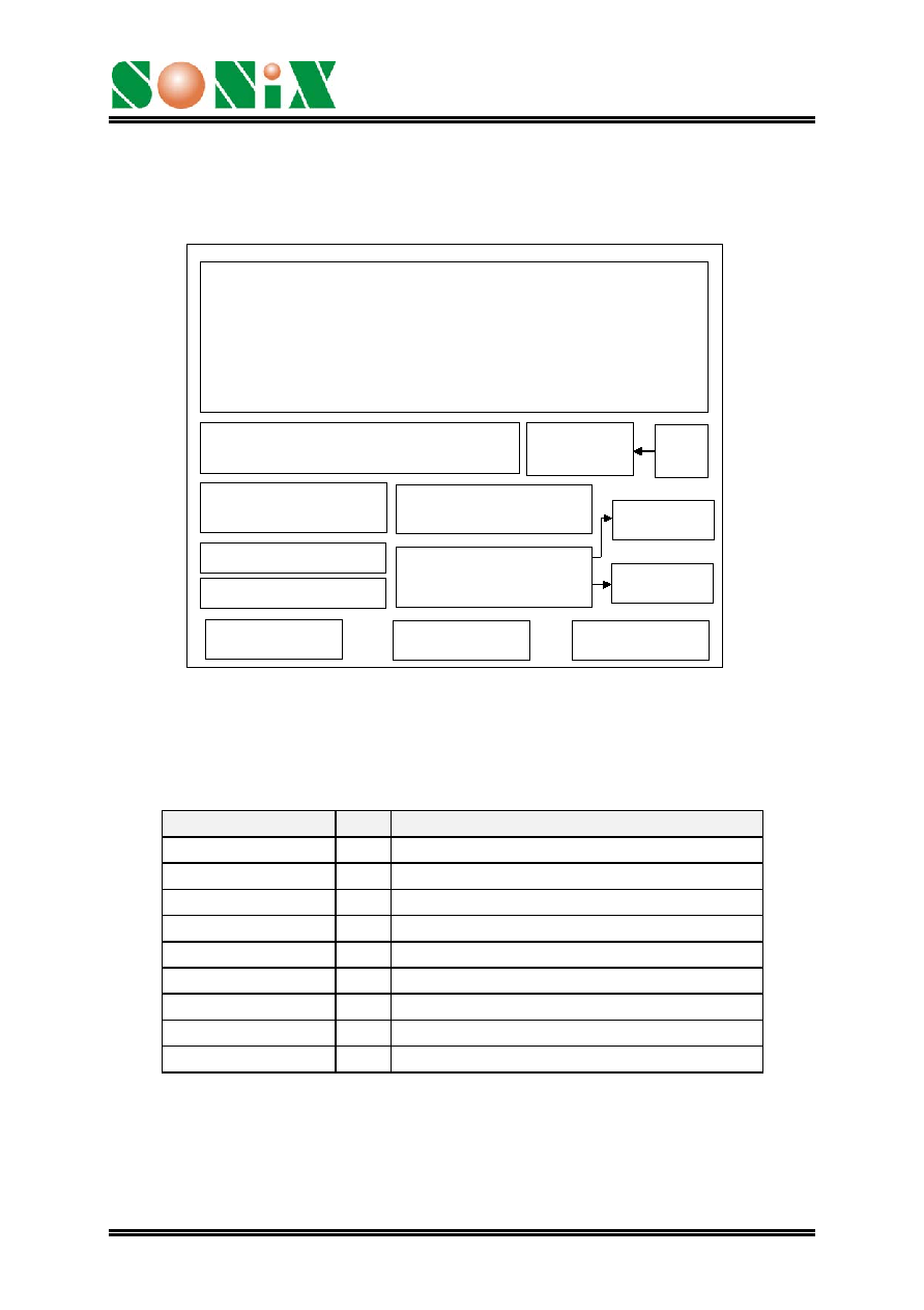
3 Block Diagram
Input port 1
IO port 2
IO port 3
Sampling Rate Counter
Timing
Generator
D/A
Timer
SRAM (64 nibbles)
ALU
Voice
Synthesizer
PWM
Address Pointers/ STACK
OSC
ROM
Program/Speech
256K
◊10 bits
4 PIN ASSIGNMENT
Symbol
I/O Function Description
P13 ~ P10
I
Bit3 ~ Bit0 of Input port 1
P23 ~ P20
I/O Bit3 ~ Bit0 of I/O port 2
P33 ~ P30
I/O Bit3 ~ Bit0 of I/O port 3
VDD
P Positive power supply
GND
P Negative power supply
RST
I
Reset pin (active high)
OSC I
Oscillator
Input
BUO1/VO O
Positive
Output of PWM or DA output
BUO2
O Negative Output of PWM
Ver: 1.0
October 23, 2002
2

SNC10B
One Channel Direct Drive Speech Controller
5 FUNCTION DESCRIPTIONS
5.1. Oscillator
SNC10B accepts RC type oscillator for system clock. The typical circuit diagram for
oscillator is listed as follows.
r
OSC
VCC
RC Oscillator
5.2. ROM
SNC10B contains substantial 256K word (10-bit) internal ROM. Program, voices and
other data are shared with this same 256K word ROM.
5.3. RAM
SNC10B contains 64 nibble RAM. The 64 nibble RAM is divided into four pages (page
0 to page 3, 16 nibble RAM on each page). In our programming structure, users can
easily define and locate RAM page in the program. For instance, users can use the
instructions, PAGEn (n=0 to 3) to switch and indicate the RAM page. Besides, users
can use direct mode, M0 ~ M15 in the data transfer type instructions, to access all 16
nibbles of each page
.
5.4. Power Down Mode
"End" instruction will power down SNC10B and enable IC to consume fewer current for
power saving. (<3uA @VDD=3V and <5uA @VDD=5V) Please be aware that when
the power down mode is activated in SNC10B, any valid data transition (L H or H L)
occurring on any input port (P1) or IO ports (P2 and P3) will lead SNC10B back to
normal operation mode.
5.5. Sampling Rate Counter
The unique sampling rate counter is designed in voice channel to be able to play
diverse voices at different sample playing rates. The playing rate can be adaptively
set up among from the wide ranges of 2.5KHz to 20KHz. This feature makes voice
close to its original source and yield the better voice quality.
Ver: 1.0
October 23, 2002
3
SNC10B
One Channel Direct Drive Speech Controller
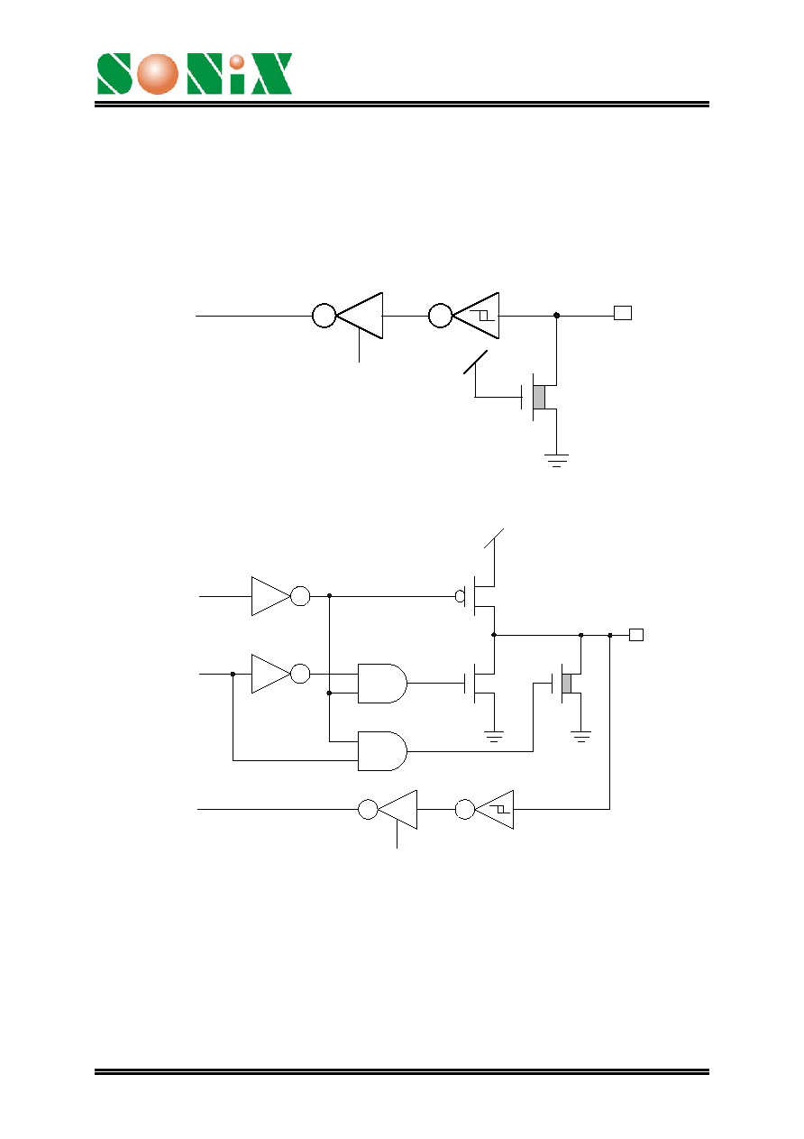
5.6. I/O Ports
P1 is a 4-bit input port, P2 and P3 are two 4-bit I/O ports. Any bit of P2 and P3 can
be programmed as either input or output port individually. Any valid data transition
(H L or L H) of P1, P2 and P3 can reactivate the chip when the chip is in
power-down mode.
To Internal Data Bus
Read Control
PAD
Weak
Input Port Configuration (P10~P13)
Port Data
Port Status
To Internal Data Bus
Read Control
PAD
Weak
I/O Port Configuration (P20~P23, P30~P33)
Note: All weak N-MOS's can serve as pull-low resistors.
Ver: 1.0
October 23, 2002
4
SNC10B
One Channel Direct Drive Speech Controller
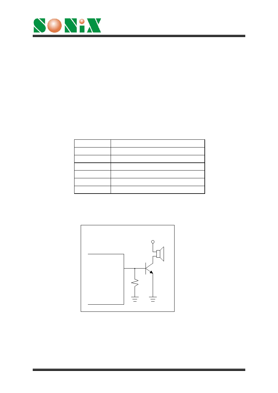
5.7. DAC & PWM
SNC10B is an advanced chip to be designed having two optimal methods to play
out the voices. One is DAC and the other is PWM. Upon user's applications, user
can select either DAC or PWM in his design. Please be aware that only one
method can be activated at a time.
DAC: A 7-bit current type digital-to-analog converter is built-in SNC10B. The
relationship between input digital data and output analog current signal is listed
in the following table. Also, the recommended application circuit is illustrated as
follows.
Input data
Typical value of output current (mA)
0 0
1 3/127
...
N n*(3/127)
...
127 3
VCC
BUO1/VO
1K
DAC output
Ver: 1.0
October 23, 2002
5