
SNC698
4-Channel Speech Controller
======== CONTENTS ========
1.
INTRODUCTION............................................................................................................... 3
2.
FEATURES ....................................................................................................................... 3
3.
BLOCK DIAGRAM ........................................................................................................... 4
4.
PIN ASSIGNMENT ........................................................................................................... 4
5.
FUNCTION DESCRIPTIONS............................................................................................ 5
5.1
O
SCILLATOR
................................................................................................................... 5
5.2
ROM.............................................................................................................................. 5
5.3
RAM .............................................................................................................................. 5
5.4
P
OWER
D
OWN
M
ODE
...................................................................................................... 5
5.5
S
AMPLING
R
ATE
C
OUNTERS
............................................................................................ 5
5.6
A
UTO
R
EPETITION
........................................................................................................... 6
5.7
I/O P
ORTS
...................................................................................................................... 6
5.8
IR F
UNCTION
.................................................................................................................. 7
5.9
8-
BIT
DAC ...................................................................................................................... 7
5.10
8-
BIT
PWM ..................................................................................................................... 8
6.
ABSOLUTE MAXIMUM RATING ..................................................................................... 9
7.
ELECTRICAL CHARACTERISTICS ................................................................................ 9
8.
ROSC PERFORMANCE................................................................................................. 10
9.
APPLICATION CIRCUIT ................................................................................................ 11
10.
BONDING PAD........................................................................................................... 13
Ver: 1.2
August 26, 2003
1

SNC698
4-Channel Speech Controller
AMENDENT HISTORY
Version Date
Description
Ver 1.1 April 24, 2003
First issue
Ver 1.2 August 26, 2003
2. FEATURES : Modify Power supply is 2.4~5.5V
5. FUNCTION Description
5.1 Oscillator : Modify ROSC R=100K
7. Electrical Characteristic : Add Current (ROSC&XTAL
Mode), and Operating Voltage Max = 5.5V
8. ROSC Performance : Add ROSC Performance
9. Application Circuit : Add Note about C1 close to VDD
pin of Chip
Ver: 1.2
August 26, 2003
2

SNC698
4-Channel Speech Controller
1. INTRODUCTION
SNC698 is a 85 seconds single chip 4-channel voice synthesizer IC which contains 24
I/O pins and a tiny controller. By programming through the tiny controller, users'
applications including section combination, trigger modes, output status, high
performance melody, multiple voices, and other logic functions can be implemented.
2. FEATURES
Single power supply 2.4V � 5.5V
Built in a tiny controller
85 seconds voice capacity are provided
Six 4-bit I/O ports are provided
256*4 bits RAM are provided
Maximum 64k program ROM is provided
256K*12 ROM size is provided for voice data and program
Readable ROM code data
Built in a high quality speech synthesizer
Four independent voice channels
Adaptive playing speed from 4k-40kHz is provided for all 4 channels individually
Automatic repetition for every channel
A 6-bit*8-bit Multiplier is embed to modulate the volume of synthesized voices
Two digital mixers (with saturation control) are provided
Built in a PWM Direct Drive circuit and a current output DA converters.
Built in 15 levels PWM output volume control.
System clock: 8M Hz ( RC-type or Crystal Option)
Low Voltage Reset
Ver: 1.2
August 26, 2003
3

SNC698
4-Channel Speech Controller
3. Block Diagram
IO1
IO2
IO3
IO4
IO5
Sampling Rate Counter
� 4
Timing
Generator
Volume
Control
8bit D/A
Timer
SRAM (256 nibbles)
ALU
Voice
Synthesizer
IO6
PWM
Address Pointers/ STACK
OSC
ROM
Program/Speech/Melody/Instrument waveform
256K
�12 bits
4. PIN ASSIGNMENT
Symbol
I/O Function Description
P13 ~ P10
I/O Bit3 ~ Bit0 of I/O port 1
P23 ~ P20
I/O Bit3 ~ Bit0 of I/O port 2
P33 ~ P30
I/O Bit3 ~ Bit0 of I/O port 3
P43 ~ P40
I/O Bit3 ~ Bit0 of I/O port 4
P53 ~ P50
I/O Bit3 ~ Bit0 of I/O port 5
P63 ~ P60
I/O Bit3 ~ Bit0 of I/O port 6
VDD
P Positive power supply
GND
P Negative power supply
XIN I
Crystal
In
RST
I
Chip Reset (Active high)
XOUT/OSC
O Crystal Out / Rosc In
CKSEL
I
Clock type select (Internal pull low)
`L' or floating
RC oscillator
`H'
Crystal
BUO1/VO1
O Positive Output of PWM or DA1
BUO2/VO2
O Negative Output of PWM or DA2
Ver: 1.2
August 26, 2003
4

SNC698
4-Channel Speech Controller
5. FUNCTION DESCRIPTIONS
5.1 Oscillator
SNC698 accepts crystal oscillator / ceramic resonator or RC type oscillator (selected
by pin CKSEL) for system clock. The typical circuit diagrams for oscillator are listed as
follows.
CKS EL
VDD
XOUT/ROS C
XIN
8M
H
Z
15
p
F
15
p
F
CKS EL
XOUT/ROS C
XIN
100K
S NC 698
S NC 698
8MHZ Crystal
8M Rosc
5.2 ROM
SNC698 contains 256K words (12-bit) internal ROM. Program, voices, melodies, data,
and instrument waveforms share the same ROM with the others.
5.3 RAM
SNC698 contains 256 nibble RAM. The 256 nibble RAM is separated into four pages
(page 0, page1, page2 and page 3). An implicit page indicator is utilized to specify
page address. Four instructions, PAGE0, PAGE1, PAGE2 and PAGE3, can switch
the page indicator. All 64 nibbles of each page can be accessed by direct mode (to
specify M0 ~ M63 in the data transfer type instructions.)
5.4 Power Down Mode
"End" instruction will let SNC698 enter power down mode and consumer very little
amount of current. (<3uA @VDD=3V and <5uA @VDD=5V) After SNC698 enters
power down mode, any valid data transition (L H or H L) occurring on any IO ports
(P1 to P6) lead SNC698 back to normal operation mode.
5.5 Sampling Rate Counters
4 independent sampling rate counters are dedicated to 4 individual voice channels to
play voices with different playing rates. The playing rate is programmable from 4KHz
to 40KHz. The resolution of sampling period of each sampling rate counter is 0.25 uS.
This feature helps SNC698 play sounds with accurate pitches in the case of music
instrument synthesis.
Ver: 1.2
August 26, 2003
5

SNC698
4-Channel Speech Controller
5.6 Auto Repetition
Auto repetition function helps SNC698 realize a "looping" sound automatically by
hardware without any software effort. Auto repetition function is a very useful
mechanism to implement "Sustain" sound in instrument synthesis. All 4 channels are
equipped with this function. Arbitrary lengths of looping sound are accepted by
SNC698.
5.7 I/O Ports
P1 to P6 are six 4-bit I/O ports. Any bit of each I/O port can be programmed to be input
or output individually. Any valid data transition (H L or L H) of each I/O port can
reactivate the chip when it is in power-down stage.
Port Data
Port Status
To Internal Data Bus
Read Control
PAD
Weak
I/O Port Configuration
Note: weak N-MOS's can serve as pull-low resistors.
Ver: 1.2
August 26, 2003
6

SNC698
4-Channel Speech Controller
5.8 IR
Function
P33 can be modulated with 38.5KHz square wave before sent out to P33 pin. The IR
signal can be achieved by this modulated signal.
Mode
38.5KHZ
P33
PAD
"1"
5.9 8-bit DAC
An 8-bit current type digital-to-analog converter is built-in SNC698. The relationship
between of input digital data and output analog current signal is listed in the following
table. Also, the recommended application circuit is illustrated as follows.
Input data
Typical value of output current (mA)
0 0
1 3/255
...
N n*(3/255)
...
255 3
SNC698
VO
VCC
1K
D/A Speaker Application
Ver: 1.2
August 26, 2003
7

SNC698
4-Channel Speech Controller
5.10 8-bit PWM
A PWM (pulse width modulation) circuit is built-in SNC698. PWM can convert input
digital data into pulse trains with suitable different pulse width. The maximum
resolution of PWM is 8 bits. Two huge output stage circuits are included in SNC698.
Both of them are capable of driving speaker directly. Besides, 15 level PWM output
current is provided for volume adjust function.
# VOL[3..0]
Output
Current
(VDD=3V, Vo=1.5V)
0 0000
120mA
1 0001
105mA
2 0010
90mA
3 0011
75mA
4 0100
60mA
5 0101
52.5mA
6 0110
45mA
7 0111
37.5mA
8 1000
30mA
9 1001
22.5mA
A 1010
15mA
B 1011
10.25mA
C 1100
7.5mA
D 1101
3.75mA
E 1110
3.75mA
F 1111
0mA
15 levels PWM output current control
BUO1/VO
BUO2
PWM output
Ver: 1.2
August 26, 2003
8

SNC698
4-Channel Speech Controller
6. ABSOLUTE MAXIMUM RATING
Items
Symbol
Min
Max
Unit.
Supply Voltage
V
DD
-V -0.3 6.0
V
Input Voltage
V
IN
V
SS
-0.3 V
DD
+0.3 V
Operating Temperature
T
OP
0 55.0
o
C
Storage Temperature
T
STG
-55.0 125.0
o
C
7. ELECTRICAL CHARACTERISTICS
Item
Sym. Min. Typ. Max. Unit
Condition
Operating Voltage
V
DD
2.4 3.0 5.5 V
Standby Current
I
SBY
-
-
2
5
-
-
uA V
DD
=3V
V
DD
=4.5V
Operating Current
(ROSC Mode)
I
OPR
-
-
350
1.5
-
-
uA
mA
V
DD
=3V, no load
V
DD
=4.5V, no load
(ROSC Mode)
Operating Current
(XTAL Mode)
I
OPR
-
-
800
1.5
-
-
uA
mA
V
DD
=3V, no load
V
DD
=4.5V, no load
(XTAL Mode)
I/O port Input Current
I
IH
-
-
3
10
10
30
uA V
DD
=3V, V
IN
=3V
V
DD
=4.5V,V
IN
=4.5V
I/O port Drive Current
I
OD
1.5
2
2
5
-
-
mA V
DD
=3V, V
O
=2.6V
V
DD
=4.5V, V
O
=3.8V
I/O port Sink Current
I
OS
2
4
3
8
-
-
mA V
DD
=3V, V
O
=0.4V
V
DD
=4.5V, V
O
=0.8V
D/A Output Current
I
VO
2
2
3
3
4
4
mA V
DD
=3V, V
O
=0.7V
V
DD
=4.5V, V
O
=0.7V
Oscillation Freq.
F
OSC
- 8 - MHz
V
DD
=3V
IR Carrier Frequency
Fir
-
38.5
-
KHz Fosc=8MHz
Ver: 1.2
August 26, 2003
9

SNC698
4-Channel Speech Controller
8. ROSC Performance
ROSC frequency vs VDD (Typical value, R=100K)
100k
4
5
6
7
8
9
10
11
12
1.5
2
2.5
3
3.5
4
4.5
5
5.5
6
VDD (Voltage)
ROSC (MHz)
100
k
ROSC frequency vs VDD (For various R)
4
5
6
7
8
9
10
11
12
1.5
2
2.5
3
3.5
4
4.5
5
5.5
6
VDD (Voltage)
ROSC (MHz)
82k
91k
100k
110k
120k
Ver: 1.2
August 26, 2003
10
SNC698
4-Channel Speech Controller
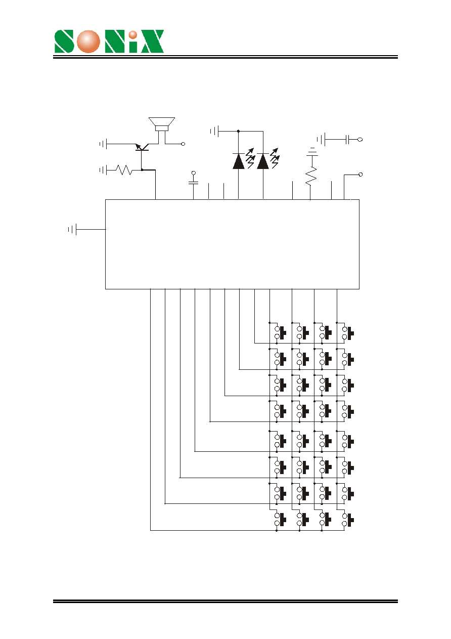
9. APPLICATION CIRCUIT
RC Oscillator, D/A Speaker Output, 32 Scan Keys
SN
C
6
9
8
G
N
D
TR
1
TR
2
TR
3
TR
4
TR
5
TR
6
P1
0
TR
7
TR
8
TR
9
TR
1
0
TR
1
1
TR
1
2
TR
1
3
TR
1
4
TR
1
5
TR
1
6
TR
1
7
TR
1
8
TR
1
9
TR
2
0
TR
2
1
TR
2
2
TR
2
3
TR
2
4
TR
2
5
TR
2
6
TR
2
7
TR
2
8
TR
2
9
TR
3
0
TR
3
1
TR
3
2
P1
1
P1
2
P1
3
P2
0
P2
1
P2
2
P2
3
P4
0
P4
1
P4
2
P4
3
P3
0
P3
1
P3
2
P3
3
OS
C
/
X
O
U
T
CK
S
E
L
XI
N
VO
1
V
D
D
1
K
8
0
5
0
100K
VD
D
VD
D
0.
1u
F
RS
T
VDD
C2
0.1uF
VD
D
C1
Note: The C1 (0.1uF) between Power and GND should be closed to VDD pin of
SNC698 as possible.
Ver: 1.2
August 26, 2003
11

SNC698
4-Channel Speech Controller
Crystal Oscillator, PWM Speaker Output, 32 Scan Keys
S
N
C
698
TR
1
TR
2
TR
3
TR
4
TR
5
TR
6
P1
0
TR
7
TR
8
TR
9
TR
1
0
TR
1
1
TR
1
2
TR
1
3
TR
1
4
TR
1
5
TR
1
6
TR
1
7
TR
1
8
TR
1
9
TR
2
0
TR
2
1
TR
2
2
TR
2
3
TR
2
4
TR
2
5
TR
2
6
TR
2
7
TR
2
8
TR
2
9
TR
3
0
TR
3
1
TR
3
2
P1
1
P1
2
P1
3
P2
0
P2
1
P2
2
P2
3
P4
0
P4
1
P4
2
P4
3
P3
0
P3
1
P3
2
P3
3
CK
S
E
L
VD
D
VD
D
GN
D
OS
C/
X
I
N
XO
U
T
20
p
f
20
p
f
8M
H
z
BU
O
2
BU
O
1
0.
1u
F
RS
T
VDD
0.1uF
VD
D
C1
C2
Note: The C1 (0.1uF) between Power and GND should be closed to VDD pin of
SNC698 as possible.
Ver: 1.2
August 26, 2003
12

SNC698
4-Channel Speech Controller
10. BONDING PAD
XO
U
T
1
2
3
4
5
6
7
8
9
10
11 12 13 14
15
16
17
18
20
21
22
23
24
25
26
27
30
29
31
32
33
34
35
28
19
(0.00, 0.00)
P10
P11
P12
P13
P20
RS
T
GN
D
VDD
BUO
2
/VO
2
GN
D
TEST
XIN
BUO
1
VO1
P63
P62
P61
P60
P53
P52
P51
P50
P43
P42
P41
P40
P32
P33
P31
P30
P23
P22
P21
GND
VDD
Note: The substrate MUST be connected to Vss in PCB layout.
Ver: 1.2
August 26, 2003
13

SNC698
4-Channel Speech Controller
Ver: 1.2
August 26, 2003
14
DISCLAIMER
The information appearing in SONiX web pages ("this publication") is believed to be
accurate.
However, this publication could contain technical inaccuracies or typographical errors.
The reader should not assume that this publication is error-free or that it will be
suitable for any particular purpose. SONiX makes no warranty, express, statutory
implied or by description in this publication or other documents which are referenced
by or linked to this publication. In no event shall SONiX be liable for any special,
incidental, indirect or consequential damages of any kind, or any damages whatsoever,
including, without limitation, those resulting from loss of use, data or profits, whether or
not advised of the possibility of damage, and on any theory of liability, arising out of or
in connection with the use or performance of this publication or other documents which
are referenced by or linked to this publication.
This publication was developed for products offered in Taiwan. SONiX may not offer
the products discussed in this document in other countries. Information is subject to
change without notice. Please contact SONiX or its local representative for
information on offerings available. Integrated circuits sold by SONiX are covered by
the warranty and patent indemnification provisions stipulated in the terms of sale only.
The application circuits illustrated in this document are for reference purposes only.
SONIX DISCLAIMS ALL WARRANTIES, INCLUDING THE WARRANTY OF
MERCHANTABILITY OR FITNESS FOR ANY PURPOSE. SONIX reserves the right
to halt production or alter the specifications and prices, and discontinue marketing the
Products listed at any time without notice. Accordingly, the reader is cautioned to
verify that the data sheets and other information in this publication are current before
placing orders.
Products described herein are intended for use in normal commercial applications.
Applications involving unusual environmental or reliability requirements, e.g. military
equipment or medical life support equipment, are specifically not recommended
without additional processing by SONIX for such application.