≠ 1 ≠
PE02965-PS
Sony reserves the right to change products and specifications without prior notice. This information does not convey any license by
any implication or otherwise under any patents or other right. Application circuits shown, if any, are typical examples illustrating the
operation of the devices. Sony cannot assume responsibility for any problems arising out of the use of these circuits.
CXA2202M
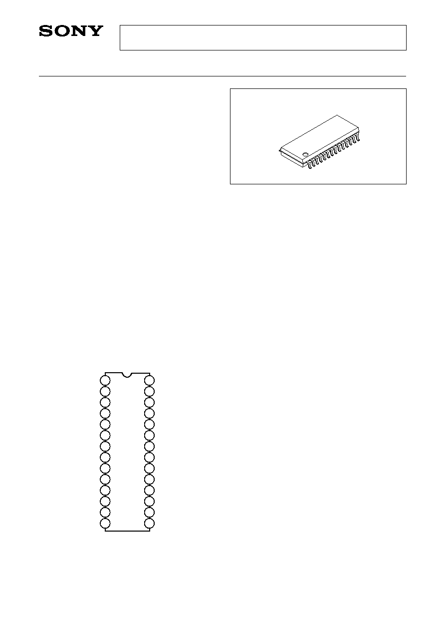
28 pin SOP (Plastic)
Preliminary
EIAJ Sound Multiplexing Decoder
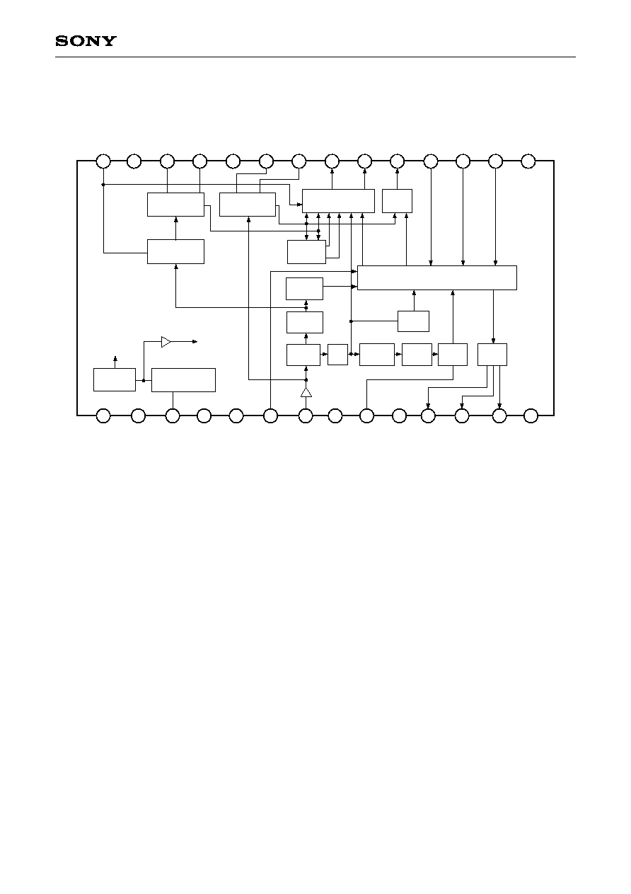
Description
The CXA2202M, is a bipolar IC designed as EIAJ
TV sound multiplexing decoder, provides various
functions including sound multiplexing demodulation,
broadcast mode identification (stereo/bilingual
discrimination display), mode display, and muting.
Features
∑ Adjustment free of filter
∑ High frequency stereo separation improved
∑ An internal active filter greatly reduces the
external parts
∑ Use of the countdown method for broadcast mode
identification eliminates the necessity of adjusting
the identification system (Cue oscillator)
∑ Internal filter eliminates interference from digital
facsimile signals
∑ The discrimination time needed to shift from
multiplexing sound to monaural sound is reduced.
∑ Output level: 520mVrms (1kHz, monaural, 100%)
∑ Forced monaural mode can be set to operate only
for stereo broadcasts or for stereo/bilingual
broadcasts.
Applications
∑ Color TVs
∑ Hi-Fi VCRs
Pin Configuration
Structure
Bipolar silicon monolithic IC
Absolute Maximum Ratings (Ta = 25∞C)
∑ Supply voltage
Vcc
10
V
∑ Input signal (Pin 7)
Vis
0.6
Vp-p
∑ Control voltage
(Pins 6, 16, 17, 18)
Vic
Vcc
V
∑ Operating temperature
Topr
≠20 to +75
∞C
∑ Storage temperature
Tstg
≠65 to +150 ∞C
∑ Allowable power dissipation
P
D
1000
mW
∑ LED drive current
I
LED
10
mA
Operating Supply Voltage Range
8.5 to 9.5
V
28 SUBI
27 NC
26 SC OUT
25 SC IN
24 NC
23 MC OUT
22 MC IN
21 L OUT
20 R OUT
19 M OUT
18 FOMO
17 MUTE
16 MODE
15 NC
1
GND
2
NC
3
REFL
4
Vcc
5
NC
6
MO MODE
7
MPX IN
8
NC
9
CUBI
10
NC
11
LEDST
12
LEDSU
13
LEDM
14
NC