
VGA/SVGA/XGA digital data serial transmitter
Features
∑ 1 chip transmitter for serial transmission of 18bit color
VGA/SVGA/XGA picture
∑ On chip differential cable driver
∑ TTL/CMOS compatible interface
∑ Support 1 pixel/shiftclock mode & 2 pixel/shiftclock
mode
∑ +3.3V single power supply
∑ Low power consumption
∑ 80pin Plastic QFP Package
(Body size: 14mm
◊
14mm)
Block Digagram & Pin out
≠ 1 ≠
E97913-PS
Sony reserves the right to change products and specifications without prior notice. This information does not convey any license by
any implication or otherwise under any patents or other right. Application circuits shown, if any, are typical examples illustrating the
operation of the devices. Sony cannot assume responsibility for any problems arising out of the use of these circuits.
CXB1451Q
80 pin QFP (Plastic)
V
EE
T
BLU1 (3)
BLU1 (2)
BLU1 (1)
BLU1 (0)
GRN1 (5)
GRN1 (4)
GRN1 (3)
GRN1 (2)
V
CC
T
V
EE
T
GRN1 (1)
GRN1 (0)
RED1 (5)
RED1 (4)
RED1 (3)
RED1 (2)
RED1 (1)
RED1 (0)
V
CC
T
LPFB
LPFA
V
EE
S
V
EE
A
V
CC
A
TESTSB
V
CC
E
SDATAN
SDATAP
V
EE
E
REFREQ
IDLE
V
CC
T
RED0 (0)
RED0 (1)
RED0 (2)
RED0 (3)
RED0 (4)
RED0 (5)
V
EE
T
V
CC
T
BLU0 (0)
BLU0 (1)
BLU0 (2)
V
EE
G
V
CC
G
BLU0 (3)
BLU0 (4)
BLU0 (5)
V
EE
T
V
CC
T
GRN0 (0)
GRN0 (1)
GRN0 (2)
GRN0 (3)
GRN0 (4)
GRN0 (5)
V
EE
G
V
CC
G
V
EE
T
V
EE
G
TESTDT
PANEL1
PANEL0
CKMODE
CNTL3
CNTL2
CNTL1
V
CC
G
V
CC
T
V
EE
T
SFTCLK
HSYNC
VSYNC
V
EE
G
V
CC
G
CNTL0
BLU1 (5)
BLU1 (4)
V
CC
T
10 11
21
30
1
Encoder
PLL
Parallel
to
Serial
Converter
Cable
Driver
40
39
38
37
36
35
34
31
32
33
22
23
24
25
26
27
28
29
12 13 14 15 16 17 18 19 20
2
3
4
5
6
7
8
9
70
69
68
67
63
64
65
66
61
62
71
72
73
74
75
76
77
78
79
80
48
49
50
51
52
53
54
55
56
57
58
59
60
41
42
43
44
45
46
47
Fig. 1. Block Diagram & Pin out

≠ 2 ≠
CXB1451Q
Pin List
Power/Ground
Pin Name
V
CC
T
V
EE
T
V
CC
G
V
EE
G
V
CC
E
V
EE
E
V
CC
A
V
EE
A
V
EE
S
10, 20, 30, 40, 48, 70, 80
1, 11, 21, 31, 41, 71
25, 32, 69, 76
26, 33, 68, 75
54
51
56
57
58
TTL power surpply , should be connected to 3.3V ± 5%
TTL ground, connected to 0V
Logical core power surpply, connected to 3.3V ± 5%
Logical core ground, connected to 0V
Serial driver power surpply, connected to 3.3V ± 5%
Serial driver ground, connected to 0V
Analog power surpply, connected to 3.3V ± 5%
Analog ground, connected to 0V
Analog substrate, connected to 0V
Pin Number
Descriptions
Digital Signals
Pin Name
SFTCLK
RED1 (5 to 0)
GRN1 (5 to 0)
BLU1 (5 to 0)
RED0 (5 to 0)
GRN0 (5 to 0)
BLU0 (5 to 0)
HSYNC
VSYNC
CNTL (3 to 0)
PANEL (1, 0)
CKMODE
IDLE
SDATAP/N
REFREQ
72
14, 15, 16, 17, 18, 19
6, 7, 8, 9, 12, 13
78, 79, 2, 3, 4, 5
42, 43, 44, 45, 46, 47
34, 35, 36, 37, 38, 39
22, 23, 24, 27, 28, 29
73
74
65, 66, 67, 77
62, 63
64
49
52, 53
50
TTL in
TTL in
TTL in
TTL in
TTL in
TTL in
TTL in
TTL in
TTL in
Tx
TTL out
Shift clock, for the data fetch at rising or falling edge
Pixel data input in 1 pixcel/sftclk mode
2nd pixel data input in 2 pixel/sftclk mode
Ignored in 1 pixcel/sftclk mode
1st pixel data input in 2 pixel/sftclk mode
Hsync data
Vsync data
Control data
Panel mode select switch
Clock mode select switch
Idle mode select switch
Serial Output & Refclk request input
Refclk request detect flag
Pin Number
Type
Descriptions
Special
Pin Name
55, 61
59, 60
SFTCLK polarity / TEST function control
External loop filter
Pin Number
Descriptions
TESTSB/DT
LPFA/B
≠ 4 ≠
CXB1451Q
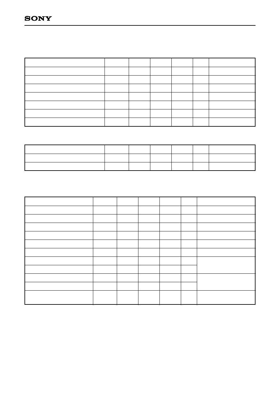
Electrical characteristics
Tab. 1. Absolute Maximum Rating
Description
Power supply voltage
TTL DC input voltage
TTL output current (High)
TTL output current (Low)
Serial output pin voltage
Ambient temperature
Storage temperature
V
CC
V
I
_T
I
OH
_T
I
OL
_T
Vsdout
Ta
Tstg
≠0.3
≠0.5
≠20
0
≠0.5
≠55
≠65
4
5.5
0
20
V
CC
+ 0.5
70
150
V
V
mA
'
mA
V
∞C
∞C
Under bias
Symbol
Min.
Typ.
Max.
Unit
Comments
Tab. 2. Recommended Operating Conditions
Description
Power supply voltage (Include V
CC
T5)
Ambient temperature
V
CC
Ta
3.135
0
3.3
3.465
70
V
∞C
Symbol
Min.
Typ.
Max.
Unit
Comments
Tab. 3. DC Characteristics (Under the recommended conditons. See Tab. 2)
Description
Input HIGH voltage (TTL)
Input LOW voltage (TTL)
Input HIGH current (TTL)
Input LOW current (TTL)
Output HIGH voltage (TTL)
Output LOW voltage (TTL)
Output HIGH current (SDATA)
Output LOW current (SDATA)
Input HIGH voltage (SDATA)
Input LOW voltage (SDATA)
Supply current
V
IH
_T
V
IL
_T
I
IH
_T
I
IL
_T
V
OH
_T
V
OL
_T
I
OH
_SD
I
OL
_SD
V
IH
_SD
V
IL
_SD
I
CC
2
≠0.5
≠400
2.3
≠0.1
14.7
V
CC
≠ 0.6
165
175
0
16
215
225
5.5
0.8
20
0.4
+0.1
17.3
V
CC
≠ 0.7
265
275
V
V
µA
µA
V
V
mA
mA
V
V
mA
mA
V
IN
= V
CC
V
IN
= 0
I
OH
= ≠0.2mA
I
OL
= 4mA
See Fig. 2
Common mode voltage
XGA, Outputs open
SVGA/VGA, Outputs open
Symbol
Min.
Typ.
Max.
Unit
Conditions

≠ 5 ≠
CXB1451Q
V
CC
A/G/E/T
V
EE
A/G/E/T
V
CC
CXB1451Q
A
52
53
55
61
A
Fig. 2. I
OH
_SD and I
OL
_SD DC measurement
Tab. 4. AC Characteristics (Under the recommended conditons. See Tab. 5)
Description
Input TTL rise time
Input TTL fall time
SFTCLK frequency
SFTCLK duty factor
Pixel/Sync/Cntl setup to SFTCLK
Pixel/Sync/Cntl hold to SFTCLK
SDATA rise time
SDATA fall time
CLOCK mode assert time
CLOCK mode deassert time
IDLE mode assert time
IDLE mode deassert time
PLL lockin time
Tir
Tir
Fsftclk
Dsftclk
Tsetup
Thold
Tor
Tof
TAclk
TDclk
TAidle
TDidle
Tlockin
0.7
0.7
20.0
10.0
38.0
19.0
60.0
30.0
40
4.0
1.0
25.0
12.5
40.0
20.0
65.0
32.5
130
10
150
350
0.1
4.8
4.8
28.0
14.0
48.0
24.0
68.0
34.0
60
400
400
ns
ns
MHz
MHz
MHz
MHz
MHz
MHz
%
ns
ns
ps
ps
ns
ns
ns
ns
ms
0.8V to 2.0V
2.0V to 0.8V
VGA, 1 pixel/sftclk mode
VGA, 2 pixel/sftclk mode
SVGA, 1 pixel/sftclk mode
SVGA, 2 pixel/sftclk mode
XGA, 1 pixel/sftclk mode
XGA, 2 pixel/sftclk mode
Vth = 1.4V
XGA 1 pixel/sftclk mode
@65MHz
See Fig. 4
20 to 80%, C
L
= 2pF
See Fig. 3
Symbol
Min.
Typ.
Max.
Unit
Conditions
V
CC
A/G/E/T
V
EE
A/G/E/T
V
CC
CXB1451Q
52
53
FET probe
Sampling
oscillo-
scope
72
TTL clock
51
51
100
Fig. 3. SDATA waveform measurement
