 | –≠–ª–µ–∫—Ç—Ä–æ–Ω–Ω—ã–π –∫–æ–º–ø–æ–Ω–µ–Ω—Ç: DS005AKC | –°–∫–∞—á–∞—Ç—å:  PDF PDF  ZIP ZIP |
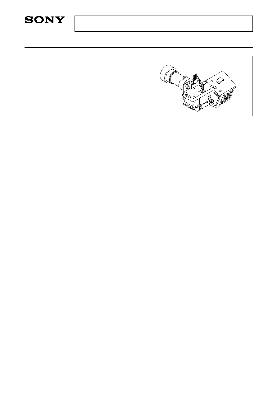
Single-Panel Liquid Crystal Optical Engine for Rear Projectors
≠ 1 ≠
E99942B04
Sony reserves the right to change products and specifications without prior notice. This information does not convey any license by
any implication or otherwise under any patents or other right. Application circuits shown, if any, are typical examples illustrating the
operation of the devices. Sony cannot assume responsibility for any problems arising out of the use of these circuits.
DS005AKC
Description
The DS005AKC is a single-panel liquid crystal
optical engine for use in rear projectors, and is
capable of full-color displays without color filters (CF).
The DS005AKC employs a square pixel arrangement
optimal for data projector applications, and allows
clear graphic and character displays. Up/down and/or
right/left inversion functions accommodate various
mounting methods.
Short projection distances are made possible through
the adoption of an ultra-wide angle lens. In addition, a
projection lens floating mechanism delivers 40 to 50
type projected images with minimal image distortion.
A high intensity discharge (HID) lamp ensures high
luminance and low power consumption.
Features
∑ Number of active dots: 1,456,000
∑ Horizontal resolution: 600 TV lines
∑ Supports SVGA (804
◊
3
◊
604)/PC98
(804
◊
3
◊
500) mode display
NTSC/NTSC-WIDE/PAL/PAL-WIDE modes also available through conversion of scanned dot numbers by an
external IC
∑ Up/down and/or right/left inverse display function
∑ Full-color display with CF-less projection system
∑ High luminance: normally-white 200 ANSIlm (typ.)
∑ Ultra-wide angle lens for short projection distances (592.8mm/39.8 type)
∑ Image distortion correction floating mechanism to support 40 to 50 type
∑ Relative luminance: 70% or more
∑ Uses HID lamp (100W)
"PC98" is a trademark of NEC Corporation.
Engine Configuration
∑ HID lamp
∑ Lamp driver (DC 300V input)
∑ High-efficiency illumination system employing an integrator
∑ Separate RGB illumination systems using dichroic mirrors (DM)
∑ LCD panel mounting mechanism, adjustable along XY
axes
∑ LCD panel (LCX021BM)
Dots: 2412 (H)
◊
604 (V) = 1,456,848 dots
∑ Wide fixed focal length lens for enlarged projection of LCD
Applications
Liquid crystal rear projection TV/monitor
≠ 2 ≠
DS005AKC
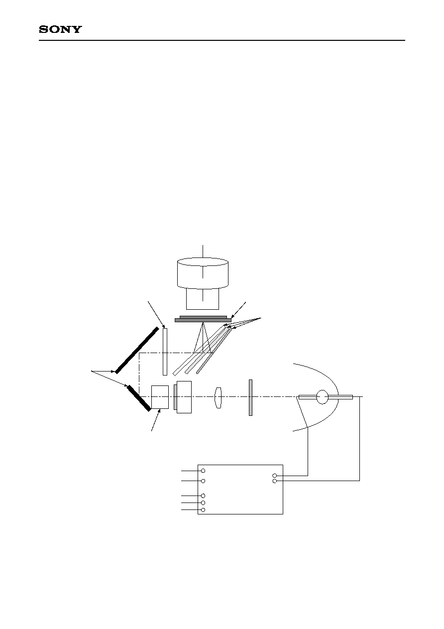
Description of Basic Operation
∑ Apply DC 300V to the lamp driver.
∑ Light emitted by the lamp is focused by an elliptical reflector and is converted to an approximately collimated
ray by a relay lens.
∑ After that the light passes through the polarizer conversion system elements and an optical integrator.
∑ Light output from the optical integrator passes through a Fresnel lens to become a collimated ray, which is
color-separated by a group of dichroic mirrors.
∑ The color-separated rays illuminate the LCX021BM evenly, and are focused on the respective RGB dots by
microlenses mounted on the LCX021BM and distributed.
∑ After transmitting the panel, the light is enlarged and projected onto a screen by a projection lens.
For details of the LCD panel operation, see the LCX021BM specifications.
Block Diagram
Lamp Driver
Positive (DC 300V)
Common
Start control input (SCI)
GND
Signal output
Connector 1
Connector 2
Lamp
UV/IR
Relay Lens
Polarization Conversion
System
Integrator
Fresnel Lens
Mirror
Dichroic Mirrors
LCD with burried Microlens Array
(LCX021BM)
Projection Lens

≠ 3 ≠
DS005AKC
Pin Description and Operating Conditions
Absolute Maximum Ratings (
measured by thermocouples)
Optical engine unit (excluding lamp driver)
∑ Operating temperature
Topr
0 to +40
∞C
∑ Panel and incident side polarizer temperature
55∞C or less (
T = 15∞C or less at an ambient temperature of 40∞C)
∑ PBS top (no contact with metal portions)
70∞C or less (
T = 30∞C or less at an ambient temperature of 40∞C)
∑ Storage temperature
Tstg
≠20 to +60
∞C
Lamp driver unit
∑ Operating temperature
Topr
0 to +65
∞C (under forced air cooling)
∑ Storage temperature
Tstg
≠25 to +85
∞C
Lamp Driver Unit
+5V
4.7k
Signal output
SCI
GND
1
2
3
Connector 2
Connector 1
1
3
To lamp
(Flag output)
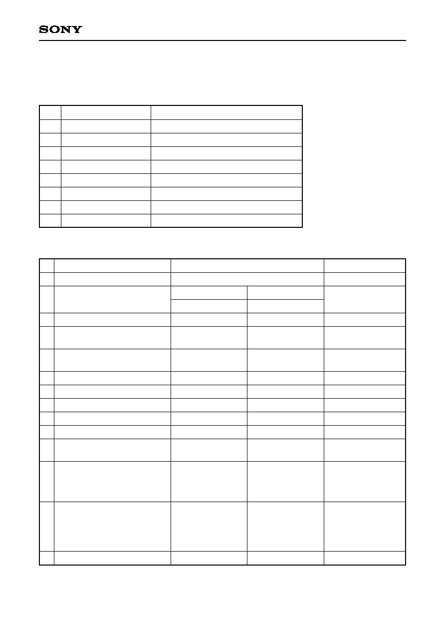
Pin Description
Operating Conditions
Connector 1
DC power supply input
Connector 2
SCI (start control input) and signal output
1
2
3
Connector
type
Positive (DC 300V)
--
Common
JST (J.S.T. Mfg. Co., Ltd.)
B 2P3-VH-B
Start control input (SCI)
GND
Signal output (flag output)
JST (J.S.T. Mfg. Co., Ltd.)
B 3B-PH-K
Input voltage
Power consumption
Circuit loss
Lamp output
Lamp startup peak voltage
Start control input (SCI)
Input voltage
Lamp extinguish
Lamp light
Signal output (flag output)
Output voltage
Lamp extinguish
Lamp light
Min.
220
107
--
95
--
≠1
3.5
0
3.5
Typ.
310
110
10
100
20
0
5.0
0.4
4.5
Max.
410
120
20
105
25
1.0
7.0
1.0
7
Unit
V
W
W
W
kV
V
V
V
V
Remarks
Input current < 1.0mA
4mA < Input current < 15.0mA
For details of the LCD panel operating conditions and pin description, see the LCX021BM specifications.

≠ 4 ≠
DS005AKC
Electro-optical Characteristics
(Ta = 25∞C)
Basic Measurement Conditions
(1) LCD driving voltage
HV
DD
= 15.5V, VV
DD
= 15.5V, VVC = 7.0V, Vcom = 6.6V
(2) Lamp output
100W
(3) Cooling conditions
Forced air cooling by DC fans
(4) Measurement temperature
25∞C unless otherwise specified.
(5) Measurement point
One point in the center of the screen unless otherwise specified.
(6) Measurement system
The measurement system is as shown below.
(7) Video input signal voltage Vsig
Vsig = 7.0 ± VAC [V] (VAC = signal amplitude)
LCD driver circuit
Projected size 101.6cm
Measurement System
I
25∞C
25∞C
x
y
x
y
x
y
x
y
u'v'
Symbol
CR25
L
Rx
Ry
Gx
Gy
Bx
By
Wx
Wy
u'v'w
Measurement
method
1
2
3
4
Min.
130
150
0.570
0.300
0.255
0.635
0.125
0.030
0.240
0.300
--
Typ.
180
200
0.600
0.340
0.295
0.675
0.155
0.060
0.280
0.340
0.015
Max.
--
--
0.640
0.380
0.335
0.715
0.185
0.090
0.320
0.380
0.025
Unit
--
ANSIlm
CIE
standards
Item
R
G
B
W
W
Contrast ratio
Luminous intensity
Chromaticity
Color shading
≠ 5 ≠
DS005AKC
1. Contrast ratio
Contrast ratio (CR) is given by the following formula.
L (White): Surface illuminance of the screen at the input signal amplitude VAC = 0.5V.
L (Black): Surface illuminance of the screen at VAC = 4.5V.
Both luminances are measured by Measurement System
I
.
CR = L (White)/L (Black)
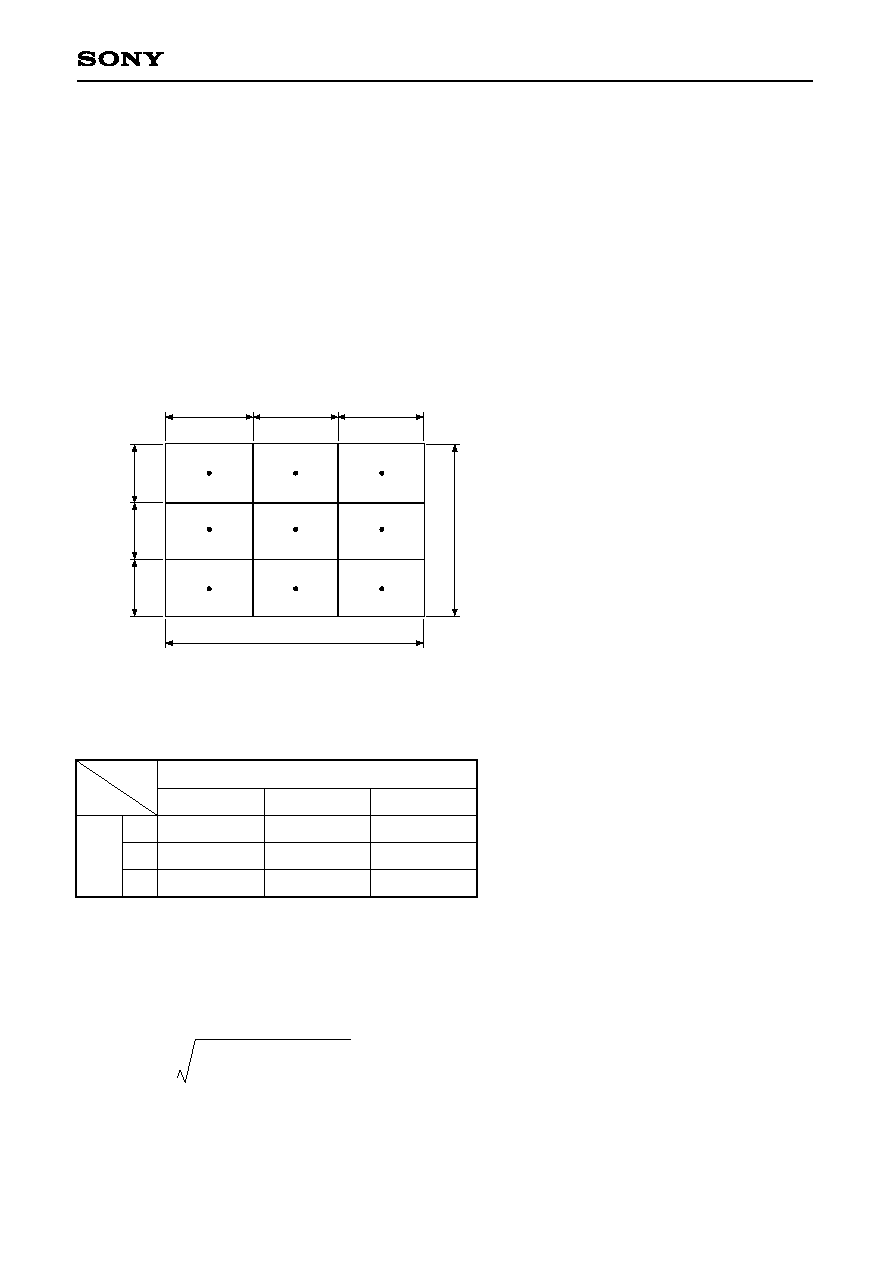
2. Luminous intensity
In Measurement System
I
, the average of the illuminance at the nine points specified in the ANSI standards
when the input signal amplitude VAC is 0.5V, multiplied by the projection area, is computed.
L = average illuminance at nine ANSI points (lm/m
2
)
◊
projection area (m
2
)
Nine ANSI points: centers of each of the
areas obtained by dividing
the effective display area
into nine smaller areas
3. Chromaticity
Raster modes of each color are defined by the representations at the input signal amplitude conditions shown
in the table below. Measurement System
I
uses chromaticity of x and y of the CIE standards here.
4. Color shading
In Measurement System
I
, the maximum values of CIE color differences at the three points in the middle row
of the nine ANSI points, measured at an input signal amplitude VAC of 0.5V, are used to compute the color
shading.
u'v' = (u'
1
≠ u'
2
)
2
+ (v'
1
≠ v
2
)
2
For other electro-optical characteristics, see the LCX021BM specifications.
(Unit: V)
R input
G input
B input
0.5
4.5
4.5
4.5
0.5
4.5
4.5
4.5
0.5
R
G
B
Display
raster
Signal amplitude (VAC) applied to each input
H/3
H/3
H/3
H
V
V
/
3
V
/
3
V
/
3
≠ 6 ≠
DS005AKC
Optical Characteristics
The optical performance is specified for the following projection conditions.
Projection Conditions
1
2
3
4
5
6
7
8
Item
Panel
Panel shift
Dot pitch
Maximum image height
Overscan
Effective panel size
Effective projection size
Projection magnification
1
2
3
4
5
6
7
8
9
10
11
12
13
14
Item
F number
Half angle of view
Back focus
Projection distance
Conjugate length
Panel side pupil position
Panel side pupil diameter
Screen side pupil position
Screen side pupil diameter
Focal length
Distortion aberration
Up/down
1.0H
Right/left
TV distortion
Up/down
Right/left
Center up/down
Center right/left
MTF (12.5lp/mm)
0H
to 0.5H
to 0.7H
to 0.86H
to 1.0H
Relative luminance
1.0H
Design value
1.79
at 39.2-type projection
38.1∞
25.778mm
592.8mm
820mm
≠1050mm
623.0mm
≠138.7mm
14.4mm
25.772mm
≠0.89%
≠0.97%
≠0.11%
≠0.05%
≠0.43%
≠0.18%
90%
75/70%
50/65%
50/45%
45/35%
50%
Remarks
(at
)
(from front of projection
lens bulb)
between panel and
screen
(from panel)
(from panel)
(contracting side)
(contracting side)
Sagittal/Tangent.
Setting value
1.60 type (32.4mm
◊
24.3mm)
None
13.5µm
◊
40.5µm
20.25mm
≠2.0%
1.60 type (32.4mm
◊
24.3mm)
40 to 50 type (screen size)
24.631 times/40 type (including distortion)
Projection Lens Specifications (design)
in air
at 49-type projection
38.1∞
25.519mm
752.3mm
933mm
≠1150mm
623.0mm
≠138.5mm
14.4mm
25.841mm
≠0.93%
≠1.16%
≠0.20%
≠0.11%
≠0.51%
≠0.26%
90%
75/65%
50/60%
45/30%
45/30%
50%
≠ 7 ≠
DS005AKC
2. Floating mechanism
The floating mechanism corrects image distortion between 40 and 50-type. At time of shipment, it is optimized
for a diagonal of 40-type (including 2.0% underscan), but the floating mechanism should be adjusted if the
projection size is different and image distortion becomes prominent. Recommended values for different
projection sizes are given below, but adjustments should be made such that image distortion is minimized.
Recommended floating mechanism settings
Projection size (diagonal) [type]
40
41
42
43
44
45
46
47
48
49
50
Recommended floating mechanism setting
≠1.5
≠1
≠0.5
0
0.4
0.75
1.1
1.55
1.95
2.25
2.5
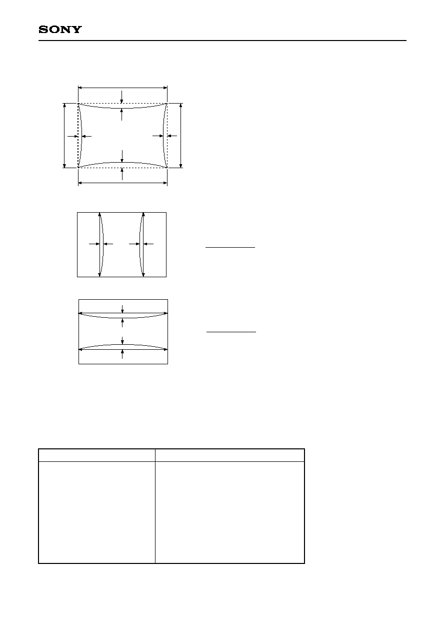
1. TV distortion
TV distortion is defined by the diagrams and formulas below.
A
B
y
y
x
x
D
C
Right/left distortion = (4x)/(A + B)
Up/down distortion = (4y)/(C + D)
y
x
A
A'
B'
B
D
D'
C'
C
A' B' C' D': Points at the four corners of the
quadrangle where center pin is most
apparent, and where the right/left
positions of A'D' and B'C' are symmetrical.
Where, A'B'
AB/2, C'D'
CD/2,
A'D'
AD/2 and B'C'
BC/2
x
B
y
B'
C'
C
A
A'
D'
D
The same measurement method and
standard values are used for center
barrel.
4x and 4y
A'B' + C'D'
4x and 4y
A'D' + B'C'

≠ 8 ≠
DS005AKC
3. Panel position adjustment range
Adjustment of the LCD panel registration is possible in the horizontal (
h) and vertical (
v) directions. The
adjustment ranges are as follows.
Horizontal adjustment (
h): ±0.5mm
Vertical adjustment (
v): ±1.0mm
Angular adjustment (
) is included in the vertical adjustment.
Service Parts
The following is a list of service parts.
Part number
DS-B011
DS-B012
DS-B003
DS-B004
DS-B015
Name
Lamp unit
Lamp driver
Polarizer unit
Projection lens
Integrator unit
Configuration
Lamp + lamp housing
Polarizer + polarizer holder
Polarization conversion element + integrator
Remarks
1
2
3
4
5

≠ 9 ≠
DS005AKC
Notes on Handling
(1) Cooling
1) This optical engine is provided with fans to cool the panel and lamp unit. However, the set should be
designed for enough ventilation and convection to ensure sufficient cooling.
2) The lamp should under no circumstances be lit while the cooling fans are not operating. The cooling fans
are provided with sensor output pins to detect operation, and the lamp driver is provided with start
control input pins. The set should be designed so that if the cooling fans are not operating, the lamp
driver does not operate.
3) When using a dust filter with the ventilation orifices, reduced ventilation due to filter clogging can cause
rises in temperature, possibly damaging the LCD or other components. The temperature of the optical
engine should be controlled, and filters should be changed as appropriate.
(2) Lamp unit
1) In order to prevent burns and other accidents, do not directly touch the lamp housing while the lamp is lit
or immediately after it has been extinguished.
2) Because of the extremely high focusing power of the ellipsoid reflector, if it is not installed in the
specified position, damage to the engine or other problems may arise. Ensure that, if the lamp housing
is not mounted in the specified position when changing the lamp, the lamp power supply will not
operate.
3) Always use the included lamp driver to light the lamp. If the lamp is turned on and off repeatedly in short
cycles, the lamp lifetime will be shortened.
4) The lamp is designed to be lit in a horizontal position. Ensure that the optical axis of the ellipsoid
reflector is within ±20∞ of horizontal.
5) The lamp emits ultraviolet rays while lit and immediately after being extinguished. Be sure not to look
directly at the lamp.
(3) Protection from dust and dirt
Image quality is significantly degraded by dust on the LCD panel and the polarizer. Employ a set
construction such that after dust is removed by a filter (mesh size 50µm or less) during air cooling, air is
blown into the optical engine.
1) Employ a dust resistant set construction, and operate in a clean environment.
2) Do not touch the surface of the projection lens and polarizer. The surfaces are easily scratched. When
cleaning, use a clean-room wiper with isopropyl alcohol. Be careful not to leave stains on the surface.
3) Use ionized air to blow off dust adhered to the optical engine.
(4) Static charge prevention
1) Use non-chargeable gloves, or simply use bare hands.
2) Do not touch any electrodes.
3) Wear non-chargeable clothes and conductive shoes.
4) Keep optical engines away from any charged materials.
5) Use ionized air or some other means to discharge.

≠ 10 ≠
DS005AKC
(5) Other handling precautions
1) The DM angles of this optical engine are adjusted to their optimal values, and should not be changed.
2) Do not remove or take apart the engine cover, projection lens, projection lens mount, relay lens, integrator
support, or lamp housing.
3) Light emitted from the lamp and from the projection lens may harm the eyes. Do not look directly into the
light from the lamp or lens.
4) Do not drop the optical engine.
5) Do not twist or bend the optical engine.
6) Keep the optical engine away from heat sources.
7) Do not dampen an optical engine with water or other solvents.
8) Avoid storing or using the optical engine at high temperature or high humidity, as this may result in
optical engine damages.
≠ 11 ≠
DS005AKC
2
8
0
±
5
(
5
.
6
)
(49.8)
1
3
2
+DC
-DC
1
3
2
CB2
SC1
GND
FLAG
CB1
(
5
.
8
)
C
B
2
3
2
1
CB1
73
±
0.5
4.0 max.
(22.3)
5.0
±
0.2
25
+2
0
4-
4.2 +0.2
0
3 1
5.0
±
0.2
(63)
5
.
0
±
0
.
2
1
5
0
.
0
±
0
.
5
1
4
0
.
0
±
0
.
2
Package Outline (lamp ballast unit)
Unit: mm

≠ 12 ≠
DS005AKC
(3
06
.6
)
16
1.4
14
5.2
±
0
.6
13
6.9
±
0
.6
56
.9
±
0
.5
5
6
11
8 ±
0
.2
87
59
(5
9)
10
6
5
(1
1)
9.5
9.5
20
48
55
.3
42
.1
8
5
4
0
7
3
2
2
(
8
3
.
5
)
(
8
3
.
8
)
(
1
1
5
.
9
)
(
6
6
.
3
)
4
.
0
3
-
4
.
4
+
0
.
1
0
4
◊
5
+
0
.
1
0
5
-
2
.
6
±
0
.
1
,
D
e
p
t
h
1
3
,
B
o
s
s
6
.
0
(
1
7
8
.
3
)
(
1
6
9
.
6
)
(
1
2
9
.
2
)
(
5
3
.
9
)
(
2
4
.
5
)
7
6
5
±
0
.
2
3
3
.
5
2
8
7
0
1
1
0
±
0
.
2
1
1
5
(
1
4
9
.
5
)
67
∞
12
7.6
±
0
.6
60
.3
±
0
.6
18
.7
±
0
.4
5
1
.7
±
0
.5
1
2
4
.2
±
0
.6
91
±
0
.5
(o
uts
id
e d
ia
me
te
r o
f c
ap
)
8
.
5
±
0
.
3
±
0
.
2
±
0
.
1
T
O
L
E
R
A
N
C
E
L
1
6
1
6
<
L
6
3
6
3
<
L
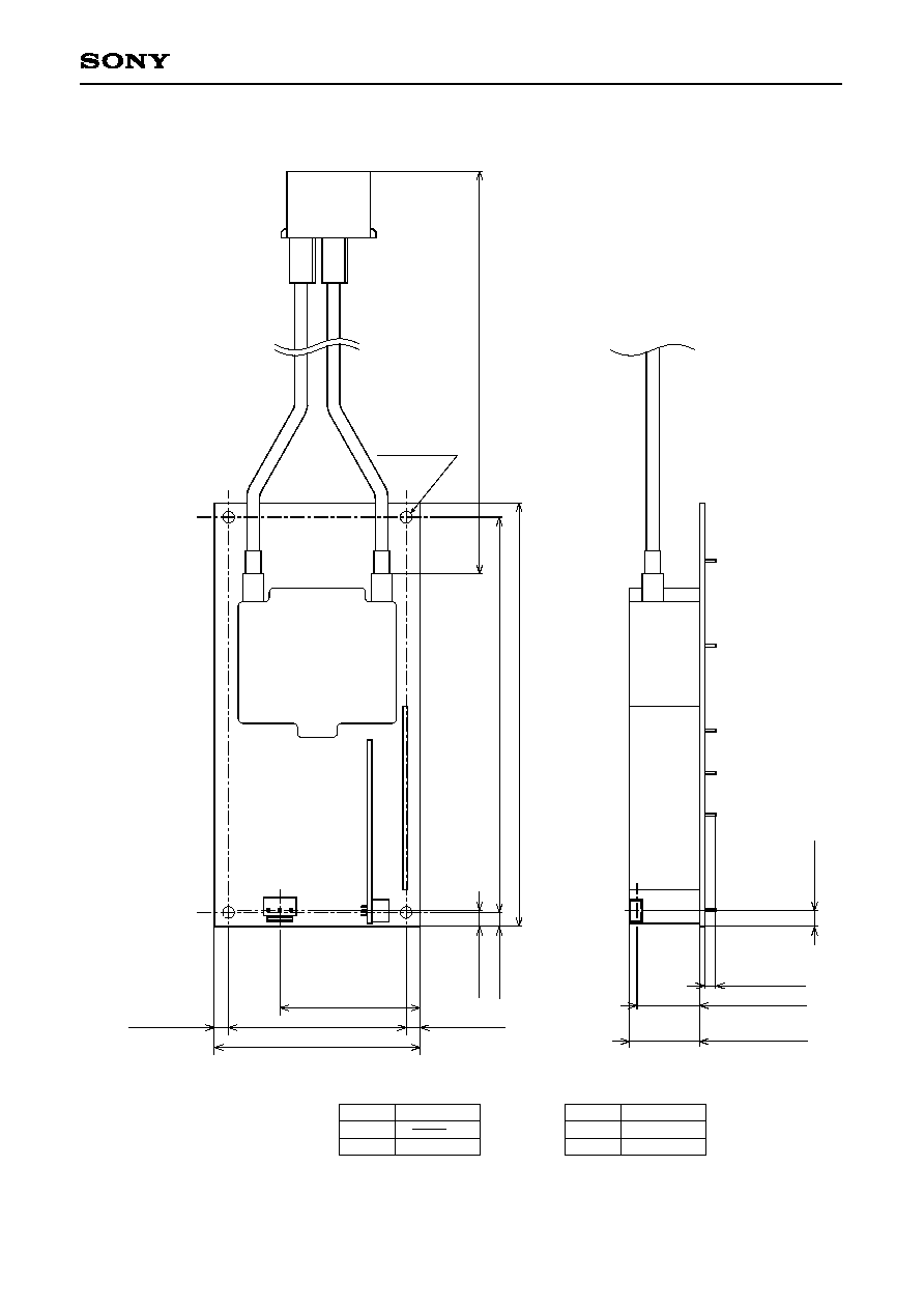
Package Outline (optical engine unit)
Unit: mm
Sony Corporation