 | –≠–ª–µ–∫—Ç—Ä–æ–Ω–Ω—ã–π –∫–æ–º–ø–æ–Ω–µ–Ω—Ç: XC-ST50CE | –°–∫–∞—á–∞—Ç—å:  PDF PDF  ZIP ZIP |

CCD B/W VIDEO
CAMERA MODULE
XC-ST50/50CE
XC-ST30/30CE
User's
G
uide
(Ver. 1.0) -- English --

XC-ST50/50CE
XC-ST30/30CE
Table of Contents
OUTLINE ................................................................................................................. 1
MAIN FEATURES .................................................................................................... 1
SPECIFICATIONS COMPARISON .......................................................................... 2
SYSTEM CONFIGURATION ................................................................................... 2
MAIN SPECIFICATIONS ......................................................................................... 3
CONNECTION DIAGRAM ....................................................................................... 4
LOCATION OF PARTS AND OPERATION ............................................................. 5
PHASE CONDITIONS OF EXTERNAL SYNCHRONIZATION ................................ 6
ELECTRONIC SHUTTER ........................................................................................ 7
RESTART RESET (R.R) ........................................................................................ 10
FRAME IMAGE OUTPUT WITH STROBE LIGHT ................................................ 12
OUTPUT WAVEFORM TIMING CHART (XC-ST50 (EIA)/XC-ST30 (EIA)) ........... 13
TIMING CHART OF EXTERNAL TRIGGER SHUTTER - MODE 1 ....................... 17
TIMING CHART OF EXTERNAL TRIGGER SHUTTER - MODE 2 ....................... 23
DIMENSIONS ........................................................................................................ 25
SPECTRAL RESPONSE CHARACTERISTICS (TYPICAL VALUE) ..................... 26
COMPARISON OF SPECTRAL RESPONSE CHARACTERISTICS (TYPICAL VALUE) .... 26
VARIOUS LENS SELECTION ............................................................................... 27

1
XC-ST50/50CE
XC-ST30/30CE
OUTLINE
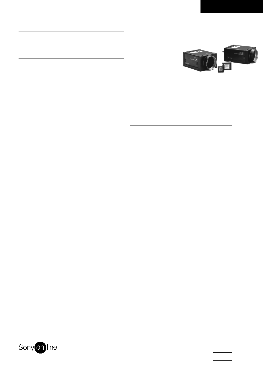
The XC-ST50/50CE and XC-ST30/30CE are compact, lightweight, black-and-white camera modules of a new
concept, which are produced as input devices for image processing by using the latest technology. These models
inherit the basic functions of the XC-75 (installing a 1/2-inch CCD) and the XC-73 (installing a 1/3-inch CCD),
which are used in various types of devices and systems and win popularity in the machine vision field. The XC-
ST50/50CE and XC-ST30/30CE provides an external trigger shutter that can catch a high-speed moving subject
using an external signal. This enables a still image to be read in arbitrary timing. These two models are compatible
with each other, thereby functioning in the same cabinet and by the same operation. The user can select a model
according to the conditions of subjects and optical conditions. In addition, the XC-ST50/50CE and XC-ST30/30CE
enable functions to be set on the rear panel for improved operability and have an internal configuration which
implements significant shock and vibration resistance, allowing easy incorporation into machine vision equipment.
MAIN FEATURES
1/2", 1/3" IT CCD
External trigger shutter function
(XC-ST50/ST30: 1/4 to 1/10,000 seconds,
XC-ST50CE/ST30CE: 1/4 to 1/8,000 seconds)
Inputting the trigger pulse gives one still image. This feature allows the capture of high-speed moving object.
Restart Reset (R.R) function
Inputting HD and VD signals (2 VD or more) continuously from the outside can catch one image at arbitrary time
and control the exposure time of CCD.
This function is used for long exposures and strobe with frame image output.
Synchronization system: Internal/external HD/VD, and VS
(VS is used only during external synchronization.)
Inputting an HD/VD signal from the outside automatically establishes external synchronization.
This function is effective for controlling multiple cameras efficiently from the external system.
Setting each mode on rear panel:
The setting of each mode can be changed by selecting DIP and rotary switch.
Almost all switches are located on the rear panel. This feature permits easy setting after equipment is installed.
Compact and lightweight
C-mount
Excellent shock and vibration resistance
Compatibility
These models are the same in the size and functions as the XC-ST70. They can be operated in the same way as
the XC-ST70 (installing 2/3-inch CCD). Therefore, they provide high compatibility.
2
XC-ST50/50CE
XC-ST30/30CE
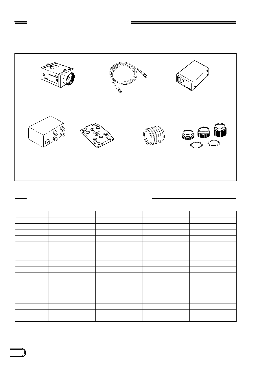
SYSTEM CONFIGURATION
The components making up the system based on XC-ST50/ST50CE or XC-ST30/ST30CE video camera are as
follows.
Tripod adaptor
VCT-ST70I (Isolated type)
Close-up ring kit
LO-77ERK
C-mount lenses
VCL-50Y-M
VCL-25Y-M
VCL-16Y-M
VCL-12YM
VCL-08YM
Junction box
JB-77
Video camera module
XC-ST50/50CE
XC-ST30/30CE
Camera adaptor
DC-700/700CE
Camera cables
CCXC-12P02N (2 m)
CCXC-12P05N (5 m)
CCXC-12P10N (10 m)
CCXC-12P25N (25 m)
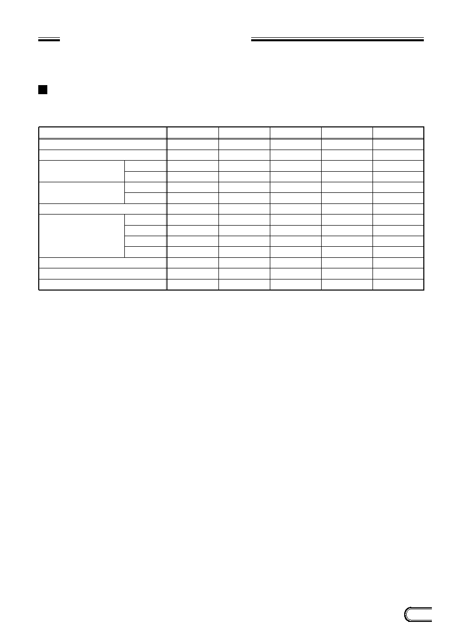
SPECIFICATIONS COMPARISON
Image device
Effective picture elements
Lens mount
Scanning system
Sensitivity
Minimum
illuminance
S/N ratio
Normal shutter
Dimensions
External trigger
shutter
Mass
Shock resistance
1/2-inch interline transfer CCD
768 (H)
x
494 (V)
C mount
2:1 interlaced
400 lx F8
0.3 lx
60db
1/100 to 1/10,000
44 (W)
x
29 (H)
x
57.5 (D) mm
110 g
10G (in the X, Y, and Z
directions at 20 to 200 Hz)
1/2-inch interline transfer CCD
768 (H)
x
494 (V)
C mount
2:1 interlaced
400 lx F4
3.0 lx
56db
1/100 to 1/10,000
44 (W)
x
29 (H)
x
71 (D) mm
140 g
7G (in the X, Y, and Z
directions at 11 to 200 Hz)
1/3-inch interline transfer CCD
768 (H)
x
494 (V)
C mount
2:1 interlaced
400 lx F8
0.3 lx
56db
1/100 to 1/10,000
44 (W)
x
29 (H)
x
57.5 (D) mm
110 g
10G (in the X, Y, and Z
directions at 20 to 200 Hz)
1/3-inch interline transfer CCD
768 (H)
x
494(V)
C mount
2:1 interlaced
400 lx F4
3.0 lx
56db
1/100 to 1/10,000
1/4 to 1/10,000
Can be changed by the
trigger pulse width or rear
panel switch.
1/100 to 1/1,600
Can be changed by the
trigger and VD. Internal
setting needs to be changed.
1/4 to 1/10,000
Can be changed by the
trigger pulse width or
rear panel switch.
1/100 to 1/1,600
Can be changed by the
trigger and VD. Internal
setting needs to be changed.
44 (W)
x
29 (H)
x
71 (D) mm
140 g
7G (in the X, Y, and Z
directions at 11 to 200 Hz)
XC-ST50
XC-75
XC-ST30
XC-73

3
XC-ST50/50CE
XC-ST30/30CE
MAIN SPECIFICATIONS
Image pickup device
XC-ST50/50CE:
1/2-inch interline transfer CCD
XC-ST30/30CE:
1/3-inch interline transfer CCD
Number of effective pixels
XC-ST50/ST30:
768(H)
x
494(V)
XC-ST50CE/ST30CE: 752(H)
x
582(V)
CCD horizontal driving frequency
XC-ST50/ST30:
14.318 MHz
XC-ST50CE/ST30CE: 14.187 MHz
CCD vertical driving frequency
XC-ST50/ST30:
15.734 kHz
XC-ST50CE/ST30CE: 15.625 kHz
Signal system
EIA/CCIR
Cell size
XC-ST50:
8.4(H)
x
9.8(V)
u
m
XC-ST50CE:
8.6(H)
x
8.3(V)
u
m
XC-ST30:
6.35(H)
x
7.4(V)
u
m
XC-ST30CE:
6.5(H)
x
6.25(V)
u
m
Lens mount
C mount
Flange back
17.526 mm
Synchronization system
Internal/external
(Selected automatically)
External sync input/output
HD/VD (2 to 5 Vp-p)
VS (Sync level: 0.3 Vp-p
+0.3V
)
*
Automatically selected according
to the existence of an input signal
when the selection switch on the
rear panel is set to EXT.
Allowable frequency deviation of external synchronization
±
1 %
(in horizontal synchronous frequency)
Jitter
Within
±
50 nsec
Scanning system
2:1 interlaced
Non-interlaced
(during external sync input)
Horizontal resolution
XC-ST50/ST30:
570 TV lines
XC-ST50CE/ST30CE: 560 TV lines
Sensitivity
XC/ST50/50CE:
400 l
x
F8 (r=ON,0 dB)
XC/ST30/30CE:
400 l
x
F5.6 (r=ON,0 dB)
S/N ratio
XC-ST50/50CE:
60 dB/58dB
XC-ST30/30CE:
56 dB/54dB
Minimum illuminance
0.3 lx (F1.4, AGC ON)
Gain
AGC/Manual/Fixed
(Can be selected using the
switch on the rear panel.)
Gamma correction
ON/OFF
(Can be selected using the
switch on the rear panel.)
Electronic shutter
XC-ST50/ST30:
1/100 to 1/10,000 seconds
XC-ST50CE/ST30CE: 1/120 to 1/10,000 seconds
External trigger shutter
XC-ST50/ST30:
1/4 to 1/10,000 seconds
XC-ST50CE/ST30CE: 1/4 to 1/8,000 seconds
*
Set using the DIP switch on the rear panel, or
continuously variable with the trigger pulse width.
Supply voltage
+12 VDC (
+
10.5 V to 15V)
Power consumption
XC-ST50/50CE: 2.0 W
XC-ST30/30CE: 1.9 W
Operating temperature
≠5 ∞C to +45 ∞C
Storage temperature
≠30 ∞C to +60 ∞C
Performance assurance temperature
0 ∞C to +40 ∞C
Operating humidity
20 to 80 % (Non-condensing)
Storage humidity
20 to 95 % (Non-condensing)
Vibration resistance
10G
(For 20 minutes in the X, Y, and
Z directions at 20 to 200 Hz)
Shock resistance
70G
Outside dimensions
44(W)
x
29(H)
x
57.5(D) mm
Weight
110 g
Standards
UL1492, FCC Class A Digital
Device, and CE (EN50081-2 +
EN50082-2)
Other
Restart Reset function
Frame or field integration can be
selected.
Conforms to new 12-pin EIAJ
assignment.
Accessories
Lens mount cap (1)
Instruction Manual (1)
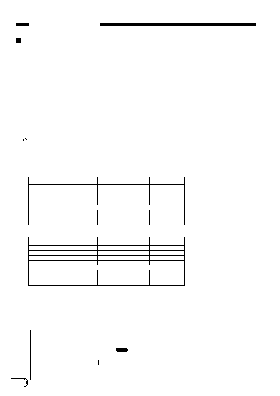
External synchronization for each mode
Mode
Normal
Normal shutter
Restart Reset
Mode 1
External trigger
shutter
Mode 2
Trigger signal
generates an
internal VD
(single) signal.
Internal sync
External sync
HD/VD
◊
: Can be used.
◊
: Cannot be used.
VS
◊
◊
◊
◊
≠0.15 V
4
XC-ST50/50CE
XC-ST30/30CE
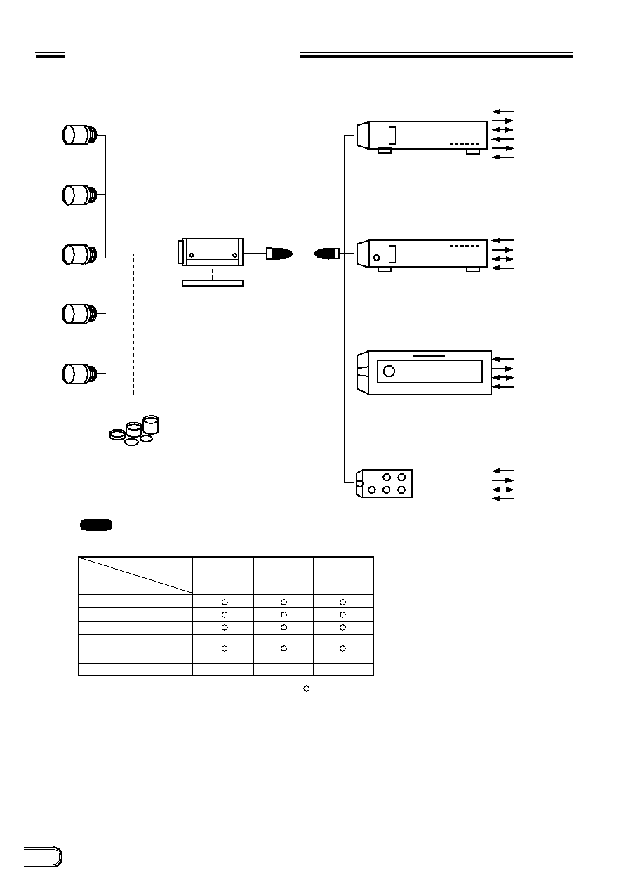
LO-77ERK
VCL-08Y-M
VCL-12Y-M
VCL-16Y-M
VCL-25Y-M
XC-ST50/50CE
XC-ST30/30CE
Tripod adaptor
VCT-ST70I
CCXC-12P02N
C-mount lens
Close-up ring kit
VCL-50Y-M
AC
VIDEO OUT
VS
*
2
HD/VD
*
1
AC
VIDEO OUT
VS
*
2
HD/VD
*
1
AC
VIDEO OUT
VS
*
2
HD/VD
*
1
TRIG
WEN
DC +12 V
VIDEO OUT
VS
*
2
HD/VD
*
1
Camera cable
Camera adaptor
DC-77RR/CE
(No trigger input terminal is provided.)
Camera adaptor
DC-777/CE
(No trigger input terminal is provided.)
Camera adaptor
DC-700/CE
(Conforms to new EIAJ and uses 12-pin assignment.)
Junction box
JB-77
(No trigger input terminal is provided.)
CCXC-12P05N
CCXC-12P10N
CCXC-12P25N
*
1: An HD/VD signal cannot be used simultaneously with a VS signal.
*
2: A VS signal cannot be used simultaneously with an HD/VD signal.
: All functions of the XC-ST50/50CE and XC-ST30/30CE cannot
be used when using DC-777/CE, DC-77RR/CE, and JB-77.
Refer to the table shown below.
XC-ST30/30CE
XC-ST50/50CE
Normal
Normal shutter
Restart Reset (R.R)
Restart Reset (R.R)
+
shutter
External trigger shutter
DC-777/CE
DC-77RR/CE
JB-77
◊
◊
◊
: Can be used.
◊
: Cannot be used.
Note
CONNECTION DIAGRAM
5
XC-ST50/50CE
XC-ST30/30CE
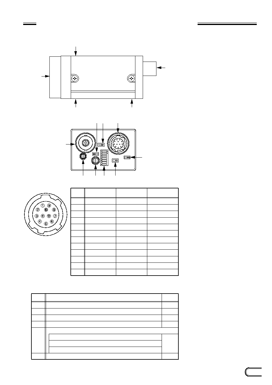
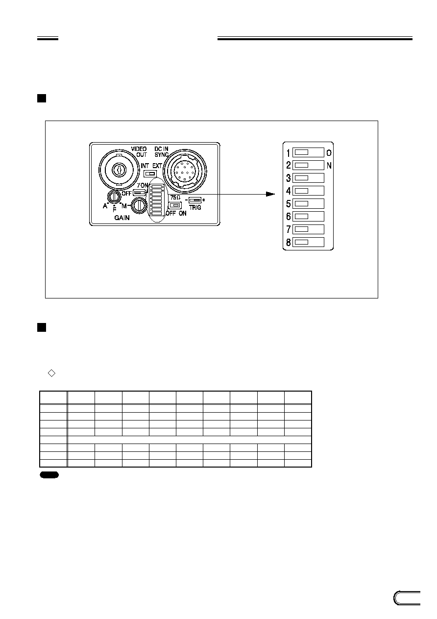
LOCATION OF PARTS AND OPERATION
1
Lens mount section
A commercial C-mount lens as well as a
Sony standard lens can be used.
2
Camera mounting reference hole
These screw holes are positionned with
high precision related to CCD sensor.
3
Screw hole for tripod adaptor mounting
(VCT-ST70I)
4
12-pin multi-connector
DC IN/SYNC (DC power/sync signal input)
5
BNC connector
VIDEO OUT
6
correction
ON/OFF selector switch
7
Internal/external sync selector
switch
The camera operates with internal syn-
chronization when there is no external
sync input signal in the EXT position.
In this case, an HD/VD signal is not out-
put from the 12-pin multi-connector.
8
Trigger polarity selector switch
This switch can select the polarity (nega-
tive or positive) of a trigger pulse.
9
75
termination selector switch
0
Selection DIP switch
Switches 1 to 4:
Selects the shutter speed.
Switch 5: Selects the frame or field
Switches 6 to 8:
Selects the normal shutter,
external trigger shutter, and
restart/reset.
A
GAIN switch
A: Outputs a fixed-level video signal ac-
cording to the brightness of a sub-
ject. (Variable range: 0 to 18 dB)
F: Fixed gain 0 dB
M: Variable gain (Manual)
M (during factory setting):
Adjusted so that all XC-ST50/50CEs
or XC-ST30/30CEs are the same in
sensitivity (set by Sony's standard
value) according to the deviation in
sensitivity of CCD.
Valid when multiple XC-ST50/50CEs
or XC-ST30/30CEs are used for an
identical subject.
B
Volume control switch
This switch can be changed in the range
of 0 to 18 dB when the GAIN switch is set
to "M".
During factory setting, this switch is ad-
justed to the fixed sensitivity for a stan-
dard subject.
4
5
2
3
2
1
3
A
5
B
=
9
4
8
6 7
Pin No.
1
2
3
4
5
6
7
8
9
10
11
12
GND
+12 V
GND
VIDEO output
GND
External HD input
*
1
External VD input
GND
≠
*
2
WEN output
TRIG input
GND
External HD/VD
synchronization
Internal HD/VD
synchronization
External VS
synchronization
GND
+12 V
GND
VIDEO output
GND
Internal HD output
Internal VD output
GND
≠
*
2
WEN output
TRIG input
GND
GND
+12 V
GND
VIDEO output
GND
≠
VS
GND
≠
*
2
WEN output
TRIG input
GND
*
1: An input VD signal is required when the restart/reset mode is used.
*
2: A WEN output signal is valid only in the external trigger shutter mode.
Corresponding
No.
6
7
8
9
0
A
correction ON/OFF selector switch
Internal/external sync selector switch
Trigger polarity selector switch
75
termination selector switch
Selection DIP switch
1, 2, 3, 4: Selects the Shutter speed.
5: Selects the field and frame integration.
6, 7, 8: Selects the normal shutter, external trigger shutter, and restart/reset.
GAIN switch
Switch
Factory-setting
mode
OFF
EXT
+
ON
OFF
(All set to
the left.)
FIX
XC-ST50/50CE
XC-ST30/30CE
(XC-ST50 model)
4
12-pin multi-connector
∑
Factory-setting mode of rear panel
CCD
VIDEO CAMERA MODULE
XC-ST50
6
XC-ST50/50CE
XC-ST30/30CE
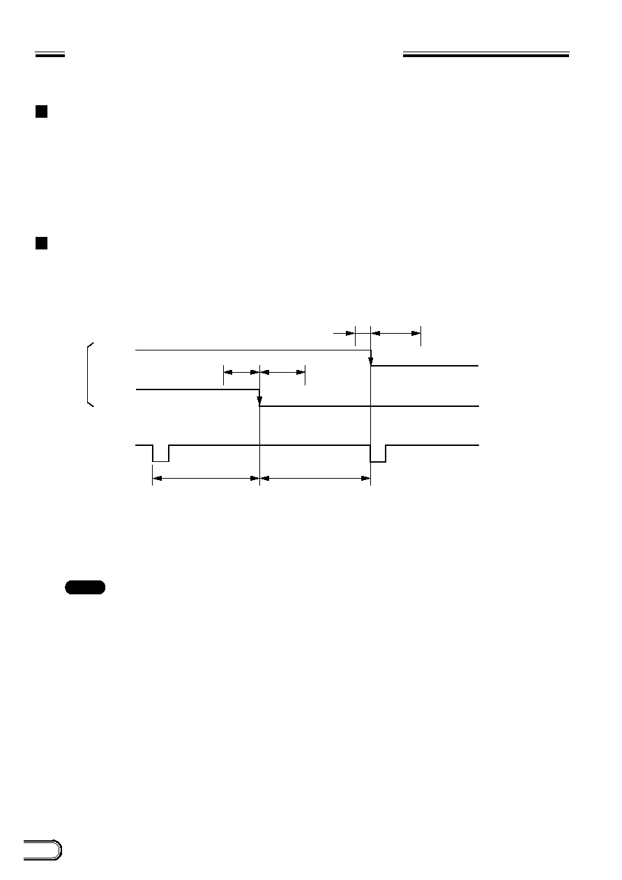
PHASE CONDITIONS OF EXTERNAL
SYNCHRONIZATION
External synchronization for each mode
∑
For normal video/normal shutter
Continuous HD/VD signal (should conform to EIA and CCIR frequencies in the timing shown in the figure below.)
∑
For Restart Reset (RR)/external trigger shutter
Continuous HD signal. The phase between VD (reset) and HD signals is as specified in the figure below in any
timing.
Phase conditions
The phase relation between external input HD and VD signals should be set as shown below with respect to the
specified center phase.
Note
: The synchronized VD signals are delayed for 1H at HD/VD external synchronization mode, while
there is no VD signal delay at VS external synchronization mode.
100
200
455 (454)
455 (454)
5
200
EXT-VD
ODD
(EVEN)
EVEN
(ODD)
EXT-HD
The operation in parentheses refers to XC-ST50CE/ST30CE.
Unit: Clock
1 CLK = 69.84 n sec (XC-ST50/ST30)
= 70.48 n sec (XC-ST50CE/ST30CE)
7
XC-ST50/50CE
XC-ST30/30CE
ELECTRONIC SHUTTER
Two types of electronic shutter are provided "normal shutter and external trigger shutter".
The electronic shutter speed and type can be set using the DIP switch on the rear panel.
DIP switch on the rear panel
Normal shutter
This mode provides continuous video output with the electronic shutter selected by switches to clearly capture a
high-speed moving object.
Setting of normal shutter speed
Switches 1 to 4: Selects the shutter speed.
Switch 5:
Selects the frame or field integration.
Switches 6 to 8: Selects the normal shutter, external trigger shutter, and Restart Reset.
Rear panel
DIP switch
Switch
1
2
3
4
5
6
7
8
Shutter
Off
0
0
0
0
≠
≠
≠
1/125
1
0
0
0
≠
≠
≠
1/250
0
1
0
0
≠
≠
≠
1/500
1
1
0
0
≠
≠
≠
1/1000
0
0
1
0
≠
≠
≠
1/2000
1
0
1
0
≠
≠
≠
1/4000
0
1
1
0
≠
≠
≠
1/10000
1
1
1
0
≠
≠
≠
*
Flickerless
≠
≠
1
≠
≠
≠
Frame: 0 / Field: 1
*
In the flickerless mode, the normal
shutter speed is 1/100
sec for
XC-ST50/ST30 (EIA)
and 1/120 sec for
: It is recommended to set DIP switch 5 for field selection. (The field selection is about two times in sensitivity as high as the frame selection.)
1: ON
0: OFF
≠: Any
Note
8
XC-ST50/50CE
XC-ST30/30CE
ELECTRONIC SHUTTER
External trigger shutter
By inputting an external trigger, a high-speed moving subject can be caught at an exact position.
Set DIP switches 6, 7, and 8 on the rear panel to mode 1 or 2. (Refer to the table below.)
When the trigger pulse width is 1/3 sec or more, the output signal is switched to a normal video signal.
There are two modes for timing in which a video signal is obtained.
∑
Mode 1 (Non-reset mode)
In this mode, a video signal synchronized with a VD signal is output after a trigger pulse is input.
∑
A video signal is synchronized with the external VD signal when an external HD/VD signal is input.
∑
A video signal is synchronized with an internal VD signal when no external HD/VD signal is input.
∑
Mode 2 (Reset mode)
In this mode, a video signal is output from a trigger pulse after a certain period of time.
*
For more details of each timing chart, refer to pages 16 to 23.
Setting of external trigger shutter speed
There are two ways to set the shutter speed.
∑
Using DIP switch on the rear panel
∑
Using trigger pulse width
Set all of DIP switches 1 to 4 on the rear panel to 0.
∑
An arbitrary shutter speed can be obtained by setting the trigger pulse width to the range of 2
µ
sec to 250
msec.
Exposure time = Trigger pulse width + 97
µ
sec (XC-ST50/ST30)
120
µ
sec (XC-ST50CE/ST30CE)
≠
≠
≠
1
0
1
1
1
0
0
0
0
1
1
0
1
0
0
0
1
1
1
1
0
0
0
1
1
0
0
1
0
0
1
1
1
0
1
0
0
1
1
0
1
1
0
0
1
1
1
1
1
0
0
1
1
Mode 1 (Non-reset mode)
≠
≠
≠
1
0
0
1
1
0
0
0
0
0
1
0
1
0
0
0
0
1
1
1
0
0
0
0
1
0
0
1
0
0
0
1
1
0
1
0
0
0
1
0
1
1
0
0
0
1
1
1
1
0
6
0
0
1
Switch
1
2
3
4
5
6
7
8
*
1/100
*
1/100
1/125
1/250
1/500
1/1000
1/2000
1/4000
**
1/10000
Frame: 0 / Field: 1
Mode 2 (Reset mode)
Switch
1
2
3
4
5
6
7
8
1/125
1/250
1/500
1/1000
1/2000
1/4000
**
1/10000
Frame: 0 / Field: 1
*
The external trigger shutter speed is set to
1/100 sec for XC-ST50/ST30(EIA) and 1/120
sec for XC-ST50CE/30CE(CCIR).
**
The external trigger shutter speed is set to
1/10000 sec for XC-ST50/ST30(EIA) and
1/8000 sec for XC-ST50CE/30CE(CCIR).
1: ON
0: OFF
≠: Any
0
0
0
0
0
1
1
0
0
0
0
0
0
1
Switch
Mode 1
(Non-reset mode)
Mode 2
(Reset mode)
1
2
3
4
5
6
7
8
Frame: 0 / Field: 1
: 1. lt is recommended to set DIP switch 5 for field selection.
(The field selection is about two times in sensitivity as high as the frame selection.)
2. After a trigger pulse is input, a new trigger pulse must not be input before the video
signal obtained by the trigger pulse has been output.
1: ON
0: OFF
Note
9
XC-ST50/50CE
XC-ST30/30CE
ELECTRONIC SHUTTER
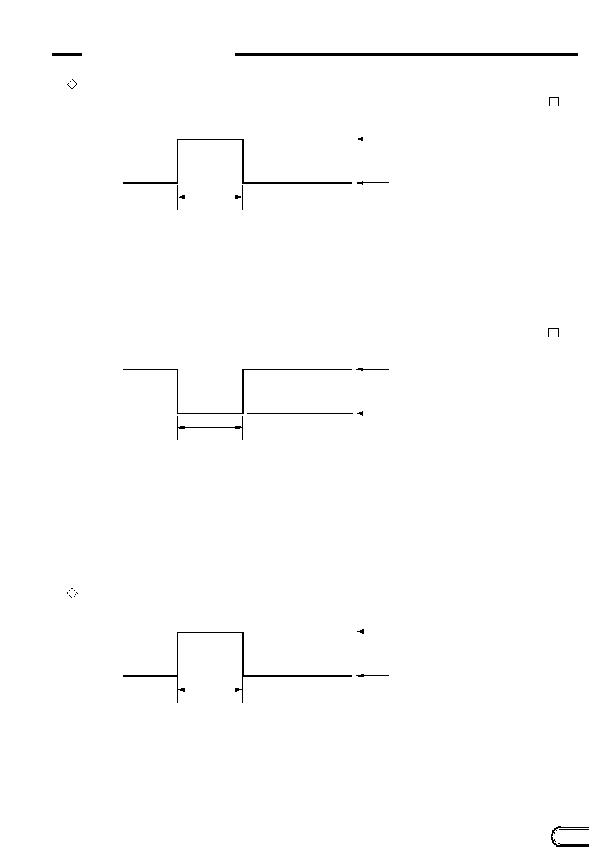
Specifications of trigger pulse
When using a trigger pulse like shown below, set the TRIG polarity selector switch on the rear panel to + :
When using a trigger pulse like shown below, set the TRIG polarity selector switch on the rear panel to ≠ :
*
Input impedance: 10 k
or more
*
The voltage and pulse width used are measured at pin 11 of a 12-pin multi-connector on the rear panel.
Specifications of WEN (Write ENable Pulse)
*
Output impedance: 10 k
or more
A
B
T
A: 2 to 5.0 V
B: 0 to 0.6 V
T: 2
µ
s to 1/4 s, 100
µ
s to 1/4 s when setting the shutter speed using DIP switch
A
B
T
A: 4.0 to 5.0 V
B: 0 to 2.0 V
T: 2
µ
s to 1/4 s, 100
µ
s to 1/4 s when setting the shutter speed using DIP switch
A
B
T
A: 5.0 V
B: 0 V
T: 15.875 ms (XC-ST50/30), 18.752 ms (XC-ST50CE/30CE)
10
XC-ST50/50CE
XC-ST30/30CE
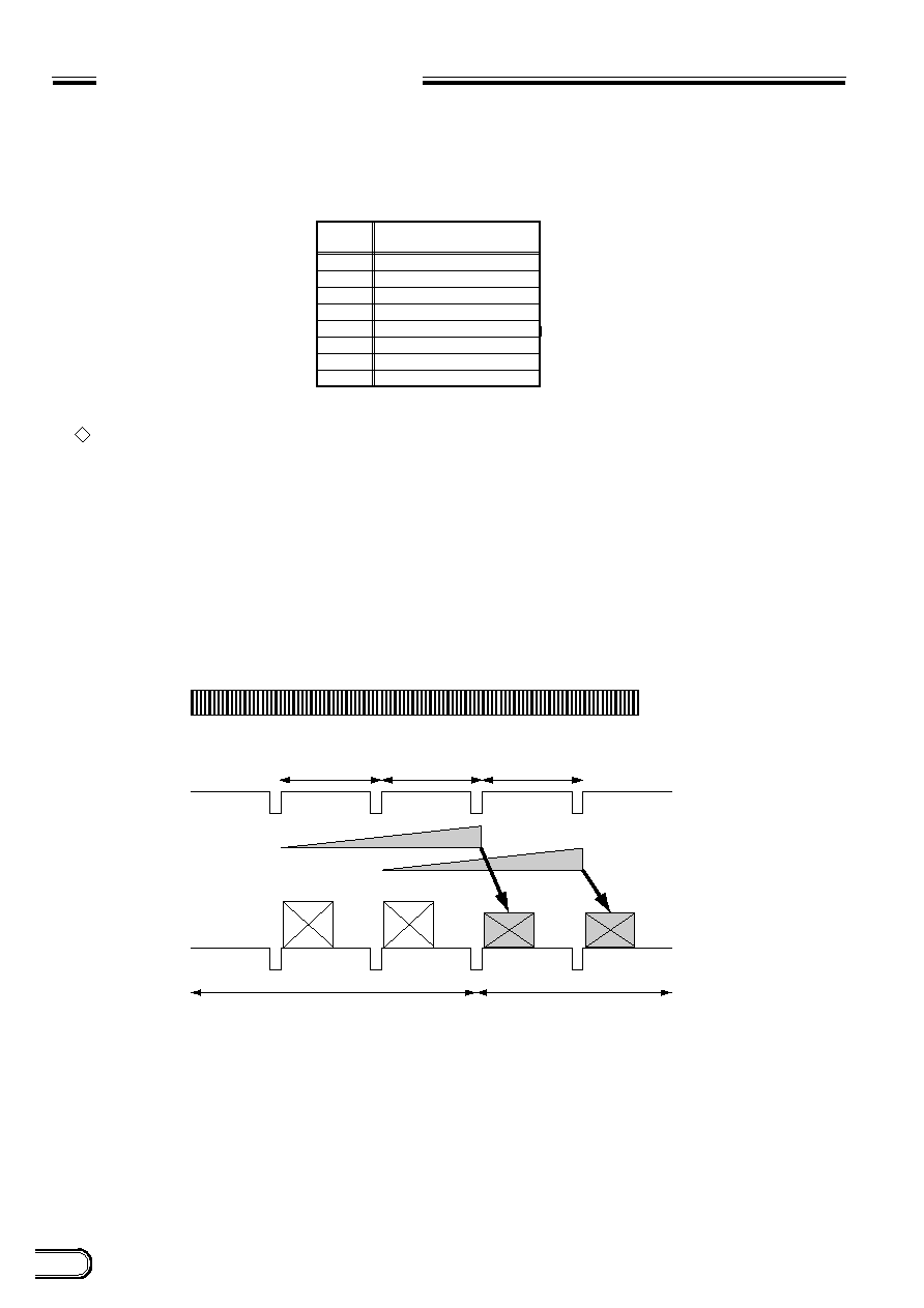
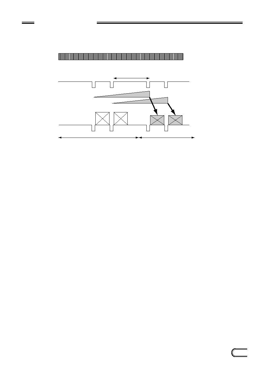
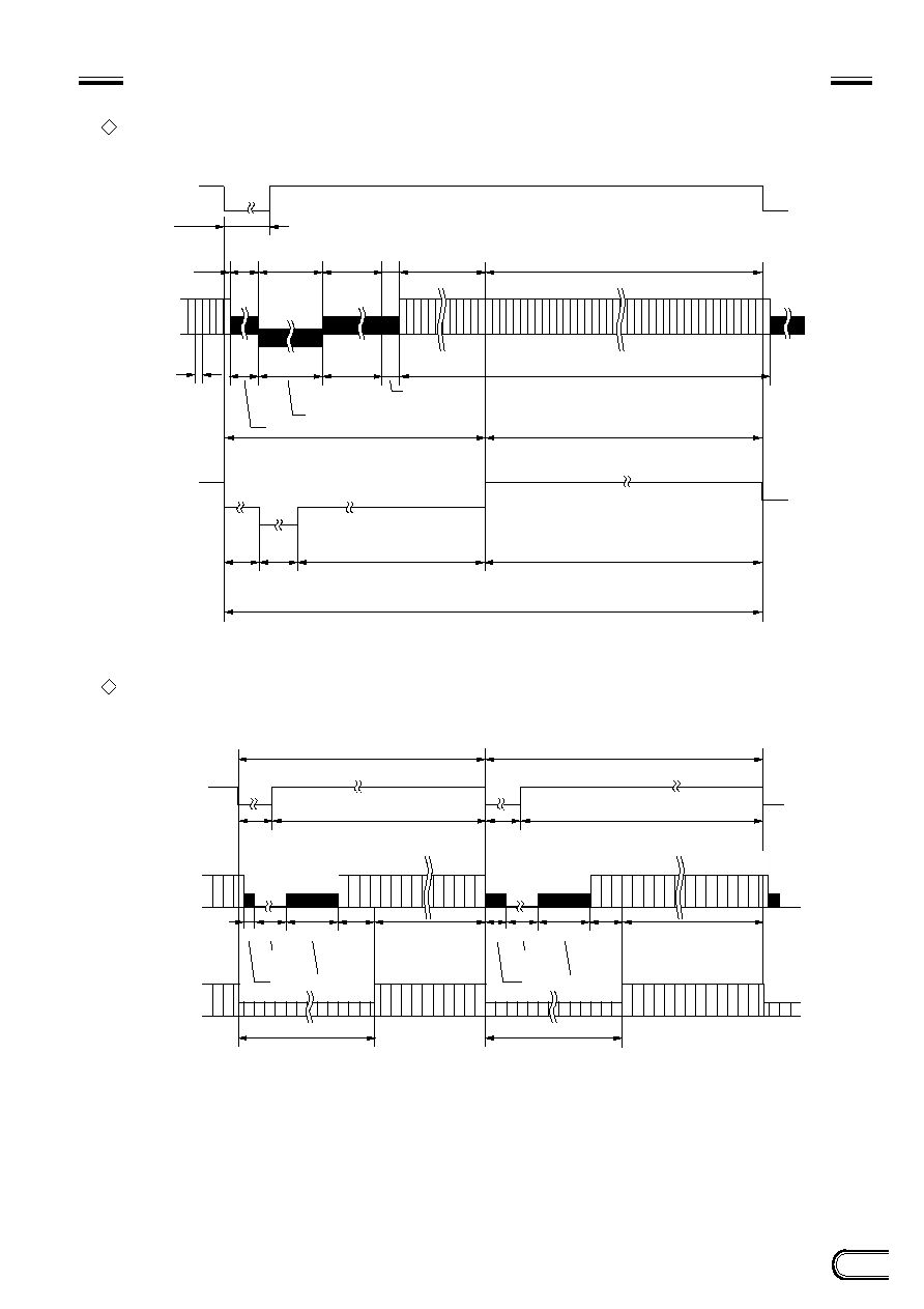
RESTART RESET (R.R)
The information on one screen can be extracted at any time by inputting a restart/reset signal (HD/VD) from the
outside. To enter this mode, set DIP switches 6, 7, and 8 on the rear panel of a camera as shown in the table below.
The setting is especially effective for the following operation.
Long exposure
A high-sensitivity image is obtained by extending the exposure time of the CCD when satisfactory sensitivity
cannot be obtained under ordinary operating conditions or when observing the trail of a moving object.
The exposure time is determined by the VD interval (T) period between external VD pulses as follows.
∑
Timing and conditions
Example 1 of Long exposure
0
0
0
0
0
1
1
1
Switch
Restart Reset (R.R)
1
2
3
4
5
6
7
8
1: ON
0: OFF
EXT HD
EXT VD
T
T
T
Video output
Odd and even fields are determined by the phase of the EXT HD/VD signal input from the outside.
Invalid image
Odd image
Even image
Valid frame image
Continuous signal: 15.734 kHz (XC-ST50/ST30), 15.625 kHz (XC-ST50CE/30CE) Allowable frequency value
±
1%
VD interval(T): 262.5H or more (XC-ST50/ST30), 312.5H or more (XC-ST50CE/30CE) and 1 second or less (Recommended)
Four or more VD pulses are required.
Exposure time for Odd field
Exposure time for Even field
11
XC-ST50/50CE
XC-ST30/30CE
RESTART RESET (R.R)
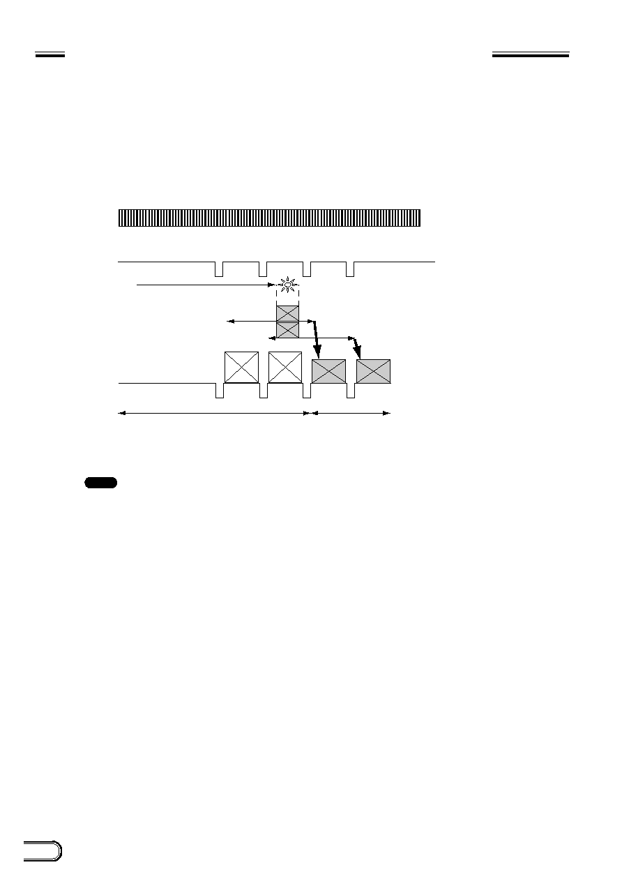
Example 2 of long exposure
EXT HD
EXT VD
T
Video output
Odd and even fields are determined by the phase of the EXT HD/VD signal input from the outside.
Invalid image
Odd image
Even image
1/60 second
1/60 second
Valid frame image
Continuous signal: 15.734 kHz (XC-ST50/ST30), 15.625 kHz (XC-ST50CE/30CE) Allowable frequency value
±
1%
VD interval(T): 262.5H or more (XC-ST50/ST30), 312.5H or more (XC-ST50CE/30CE) and 1 second or less (Recommended)
Four or more VD pulses are required.
Exposure time for Odd field
Exposure time for Even field
12
XC-ST50/50CE
XC-ST30/30CE
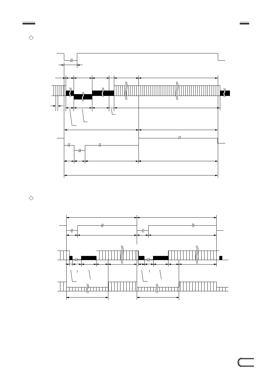
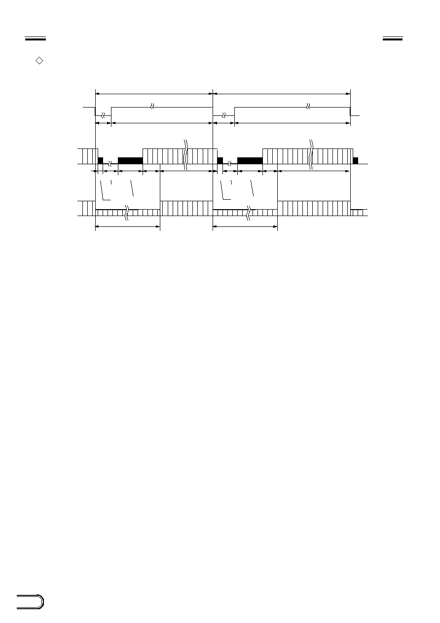
EXT HD
EXT VD
Strobe light
Video output
Invalid image
Odd image
Even image
Valid frame image
Continuous signal: 15.734 kHz (XC-ST50/ST30), 15.625 kHz (XC-ST50CE/30CE) Allowable frequency value
±
1%
VD: XC-ST50/ST30 (1/60 sec), XC-ST50CE/30CE (1/50 sec) Four or more VD pulses are required.
<Timing chart by restart/reset>
Exposure time for Odd field
Exposure time for Even field
Odd and even fields are determined by the phase of the EXT HD/VD signal input from the outside.
Avoid lighting the scene during the light-emitting inhibit zone defined below. (The field is transfered to the
storage area of the CCD, so it can be read out.)
: For best performance, it is recommended not to flash between VD and VD + 10H (XC-ST50/ST30)/
16H (XC-ST50CE/ST30CE).
Note
FRAME IMAGE OUTPUT WITH STROBE LIGHT
A full frame image with vertical resolution of 485 lines (XC-ST50/ST30) or 575 lines (XC-ST50CE/ST30CE) can be
obtained with a strobe light by firing the strobe when the exposure time of the two fields overlap.
∑
Timing and conditions
13
XC-ST50/50CE
XC-ST30/30CE
OUTPUT WAVEFORM TIMING CHART
(XC-ST50 (EIA)/XC-ST30 (EIA))
Timing chart of horizontal output waveform
Timing chart of vertical output waveform (2:1 interlaced frame integration)
91 (6.36
µ
s)
69.8 ns
40
77
22
3
15
752
Effective total pixel 768
Horizontal blanking period (11.0
µ
s)
One horizontal scanning period (1 H)
910 (63.56
µ
s)
Output video period
752 (52.5
µ
s)
67 (4.68
µ
s)
HSYNC
70
(4.89
µ
s)
21
(1.47
µ
s)
HD
Camera video
output signal
(Typical value)
CCD
output
signal
Optical black portion
Horizontal transfer stop period
Dummy
pixel
Optical black
portion
Odd field (262.5 H)
253.5 H
253.5 H
489
494
491
490
492
494
9 H
Vertical blanking
period (20 H)
Vertical blanking
period (20 H)
9 H
Even field (262.5 H)
VD
Camera
video
output
signal
CCD
output
signal
1 3 5 7 9
2 4 6 8
6
8
1
4
242.5
3.5
242.5
6
8
2
493
Optical black portion
Empty
transfer
Optical black portion
Empty
transfer
14
XC-ST50/50CE
XC-ST30/30CE
ELECTRONIC SHUTTER
OUTPUT WAVEFORM TIMING CHART (XC-ST50 (EIA)/XC-ST30 (EIA))
Timing chart of vertical output waveform (2:1 interlaced field integration)
Odd field (262.5 H)
253.5 H
253.5 H
1
2+3
4+5
6+7
8+9
1+2
3+4
5+6
7+8
488+489
490+491
489+490
491+492
493+494
9 H
Vertical blanking
period (20 H)
Vertical blanking
period (20 H)
9 H
Even field (262.5 H)
VD
Camera
video
output
signal
CCD
output
signal
6
8
1
4
242.5
6
8
1
3.5
242.5
492+493
494
Optical black portion
Empty
transfer
Optical black portion
Empty
transfer
xc
15
XC-ST50/50CE
XC-ST30/30CE
OUTPUT WAVEFORM TIMING CHART (XC-ST50CE (CCIR)/XC-ST30CE (CCIR))
Timing chart of horizontal output waveform
Timing chart of vertical output waveform (2:1 interlaced frame integration)
70.5 ns
98
(6.91
µ
s)
40
91
22
3
15
736
Effective total pixel 752
Horizontal blanking period (12.1
µ
s)
One horizontal scanning period (1 H)
908 (64.0
µ
s)
Output video period
736 (51.9
µ
s)
81 (5.71
µ
s)
HSYNC
70
(4.93
µ
s)
21
(1.48
µ
s)
HD
Camera video
output signal
(Typical value)
CCD
output
signal
Optical black portion
Horizontal transfer stop period
Dummy
pixel
Optical black
portion
Odd field (312.5 H)
305 H
305 H
1 3 5 7 9
579
581
2 4 6 8
580
7.5 H
Vertical blanking
period (25 H)
Vertical blanking
period (25 H)
7.5 H
Even field (312.5 H)
VD
Camera
video
output
signal
CCD
output
signal
287.5
6
14
1
3.5
287.5
6
14
2
3
582
Optical black portion
Empty
transfer
Optical black portion
Empty
transfer
16
XC-ST50/50CE
XC-ST30/30CE
ELECTRONIC SHUTTER
OUTPUT WAVEFORM TIMING CHART (XC-ST50CE (CCIR)/XC-ST30CE (CCIR))
Timing chart of vertical output waveform (2:1 interlaced field integration)
Odd field (312.5 H)
305 H
305 H
1
2+3
4+5
6+7
8+9
582
1+2
3+4
5+6
7+8
578+579
580+581
579+580
7.5 H
Vertical blanking
period (25 H)
Vertical blanking
period (25 H)
7.5 H
Even field (312.5 H)
VD
Camera
video
output
signal
CCD
output
signal
287.5
287.5
6
14
1
3.5
6
14
1
3
581+582
Optical black portion
Empty
transfer
Optical black portion
Empty
transfer
17
XC-ST50/50CE
XC-ST30/30CE
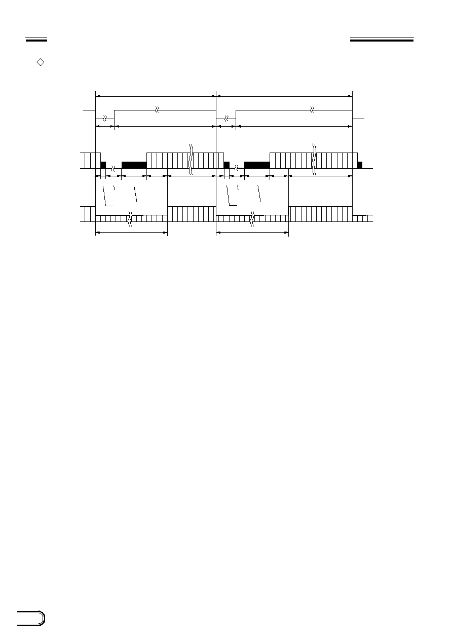
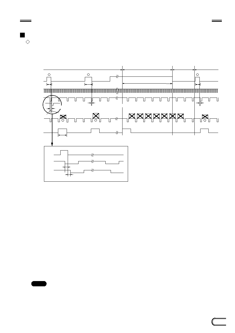
*
1
Trigger
*
1
External HD
*
1
External VD
(Continuous
VD)
EXT-VD
Video out
WEN
TRG
EXT-VD
EXT-VD
External trigger shutter operation
1/3 s or more
*
2
Exposure time Te
*
2
Exposure
time Te
*
3
Normal operation
Mode transition state
External input
inhibition area
(50 ms)
External trigger
shutter operation
10
µ
s or more
*
2
Exposure time Te
≠65
µ
s
65
µ
s
10
µ
s
+10
µ
s
*
4
T : T = Under 65
µ
s to under +10
µ
s
1
2
3
1
2
3
*
4
T : T = Under 65
µ
s to under +10
µ
s
250H (XC-ST50/30)
293H (XC-ST50CE/30CE)
*
5
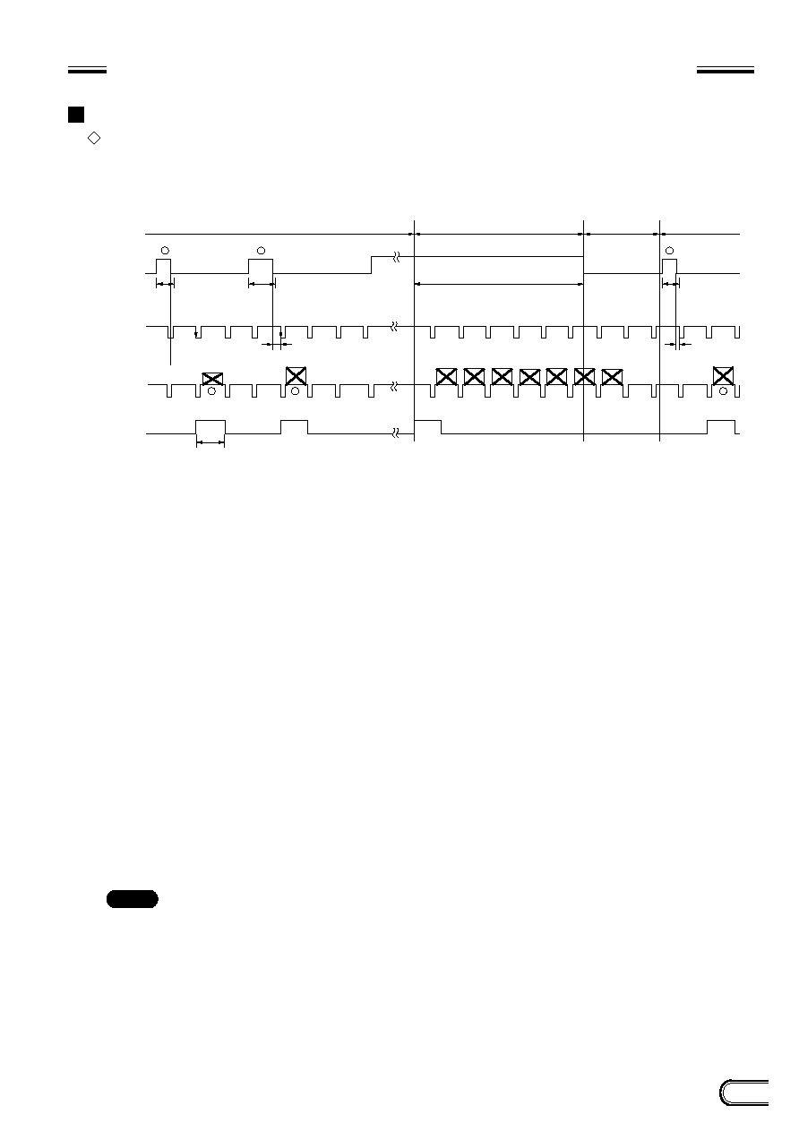
TIMING CHART OF EXTERNAL TRIGGER SHUTTER - MODE 1
(NON-RESET MODE)
For setting the shutter speed using TRG width
HD/VD input
∑
Continuous HD/VD input
*
1: This is a signal input from the outside. Be sure to input both HD and VD signals in this case.
*
2: Exposure time Te
Te = Trigger width + 97
µ
s (XC-ST50/30)
Te = Trigger width + 120
µ
s (XC-ST50CE/30CE)
(The trigger width should be between 2
µ
s and 1/4 s)
*
3: The normal operation state is engaged when the trigger high period exceeds 1/3sec. The external trigger
shutter operation is engaged when the trigger pulse goes "low". In this case, the area between the falling
edge of a trigger pulse and the subsequent 50 ms period is an external trigger input inhibition area. During
the trigger inhibit period, an input trigger may be missed.
*
4: In all cases the WEN signal indicates when a valid image is available. Normally, an image is output after
the external falling edge. If the falling edge of the trigger is very close to the falling edge of the external VD,
there may be a delay of 1VD in the output. The period of uncertainty is when the falling edge of VD is
between 65
µ
s before or 10
µ
s after the falling edge of the trigger.
*
5: When the external trigger shutter mode changes into the normal operation mode, one WEN signal is
output.
Note
: An image is superimposed when the next exposure ends before the previous image is output.
18
XC-ST50/50CE
XC-ST30/30CE
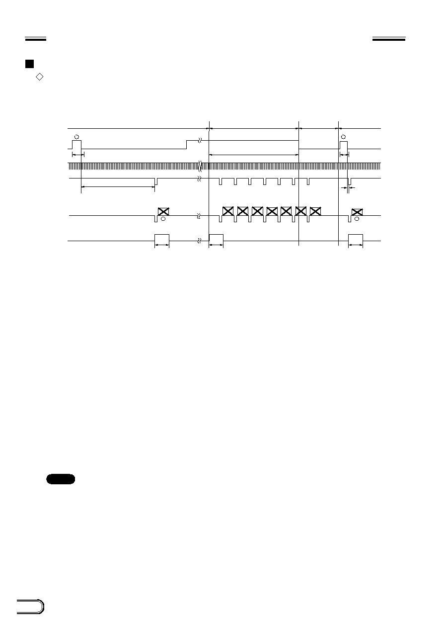
1/3 s or more
min 10
µ
s
*
4 T : T = 10
µ
s to 100 ms
250H
(XC-ST50/ST30)
293H
(XC-ST50CE/ST30CE)
250H
(XC-ST50/ST30)
293H
(XC-ST50CE/ST30CE)
250H
(XC-ST50/ST30)
293H
(XC-ST50CE/ST30CE)
*
1
Trigger
*
1
External HD
Video out
WEN
External trigger shutter operation
*
3 Normal operation
*
5
Mode transition state
External input
inhibition area
(50 ms)
External trigger
shutter operation
*
2 Exposure time Te
*
2 Exposure
time Te
1
3
1
3
*
1
External VD
(Single VD)
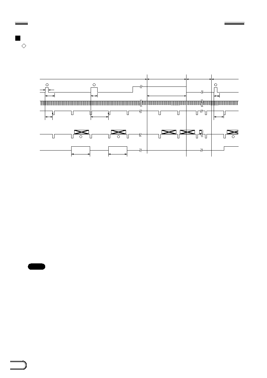
TIMING CHART OF EXTERNAL TRIGGER SHUTTER - MODE 1 (NON-RESET MODE)
For setting the shutter speed using TRG width
HD/VD input
∑
Continuous HD input and single VD input
*
1: This is a signal input from the outside. Be sure to input both HD and VD signals in this case. Make the
phase of the VD signal coincide with the falling edge of the HD signal during input operation.
*
2: Exposure time Te
Te = Trigger width + 97
µ
s (XC-ST50/ST30)
Te = Trigger width + 120
µ
s (XC-ST50CE/ST30CE)
(The trigger width should be between 2
µ
s and 1/4 s)
*
3: The normal operation state is engaged when the trigger high period exceeds 1/3 sec. After that the external
trigger shutter operation is engaged when the trigger pulse goes "low". In this case, the area between the
falling edge of a trigger pulse and the subsequent 50 ms period is an external trigger input inhibition area.
During the trigger inhibit period, an input trigger may be missed.
*
4: Be sure to input an external VD signal between 10
µ
s and 100 ms from the falling edge of a trigger pulse
(as shown by
1
and
2
in the figure). For the input (except described above), the operation cannot be
ensured. If the external VD signal is not input under the prescribed conditions, the normal operation is
engaged several V after a change in input operation under the prescribed conditions.
*
5: When the external trigger shutter mode changes into the normal operation mode, one WEN signal is
output.
Note
: An image is superimposed when the next exposure ends before the previous image is output.
19
XC-ST50/50CE
XC-ST30/30CE
*
4
Interrnal VD
1/3 s or more
*
5
T : T = 10
µ
s or more
*
6
*
1
Trigger
Video out
WEN
External trigger shutter operation
*
3
Normal operation
Mode transition state
External input
inhibition area
(50 ms)
External trigger
shutter operation
*
2
Exposure time Te
*
2
Exposure time Te
*
2
Exposure
time Te
*
5
T : T = Under 10
µ
s
1
2
3
1
2
3
250H (XC-ST50/ST30)
293H (XC-ST50CE/ST30CE)
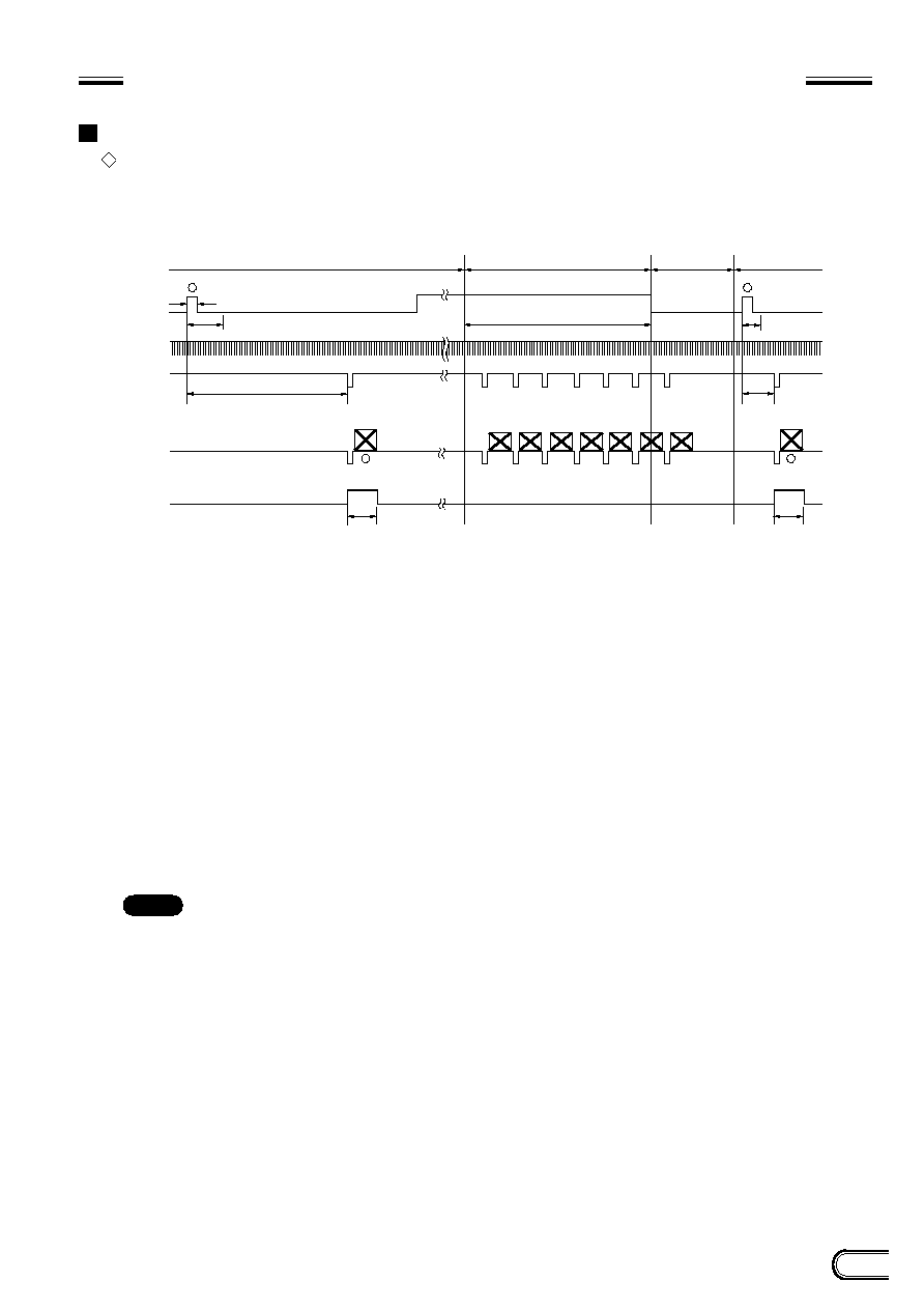
TIMING CHART OF EXTERNAL TRIGGER SHUTTER - MODE 1 (NON-RESET MODE)
For setting the shutter speed using TRG width
No HD/VD input (Internal synchronization)
*
1: This is a signal input from the outside.
*
2: Exposure time Te
Te = Trigger width + 97
µ
s (XC-ST50/ST30)
Te = Trigger width + 120
µ
s (XC-ST50CE/ST30CE)
*
3: The normal operation state is engaged when the high period exceeds 1/3 sec. After that, the external
trigger shutter operation is engaged when the trigger pulse goes "low". In this case, the area between the
falling edge of a trigger pulse and the subsequent 50 ms period is an external input inhibition area. During
the trigger inhibit period, an input trigger may be missed.
*
4: An internal VD signal is output by setting the INT/EXT switch on the rear panel to INT.
*
5: During external trigger shutter operation, an image is output when an internal VD signal falls after a trigger
pulse falls (as shown by
1
and
2
in the figure). However, if the time (T in the figure) between the falling
edges of a trigger pulse and internal VD signal is under 10
µ
s, an image is output when the internal VD
signal or the next internal VD signal falls (as shown by
3
in the figure). (In this case, an image is output
when the next internal VD signal falls.) An image and WEN signal are always output together. For more
details, refer to the WEN signal. (The falling edge of an internal VD signal is the same in phase as the
beginning of an equalizing pulse in a SYNC V area.)
*
6: When the external trigger shutter mode changes into the normal operation mode, one WEN signal is
output.
Note
: An image is superimposed when the next exposure ends before the previous image is output.
20
XC-ST50/50CE
XC-ST30/30CE
1/3 s or more
*
1
Trigger
*
1
External HD
Video out
WEN
*
1
External VD
(Continuous
VD)
External trigger shutter operation
*
3
Normal operation
Mode transition state
External input
inhibition area
(50 ms)
External trigger
shutter operation
*
4
T : T = Under 10 ms
*
4
T : T = 10 ms or more
*
4
T : T = 10 ms or
more
*
2
Exposure time Te
100
µ
s to 250 ms
*
2
Exposure time Te
*
2
Exposure
time Te
250H (XC-ST50/30)
293H (XC-ST50CE/30CE)
250H (XC-ST50/30)
293H (XC-ST50CE/30CE)
1
2
3
1
2
3
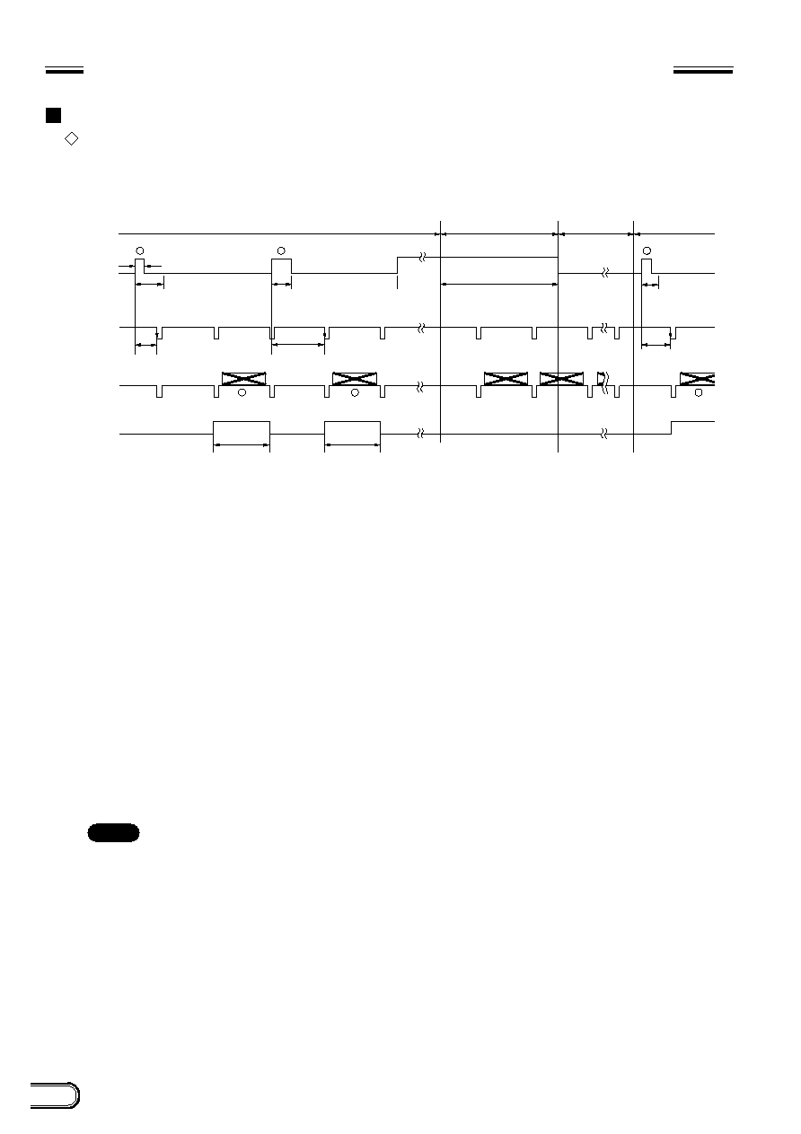
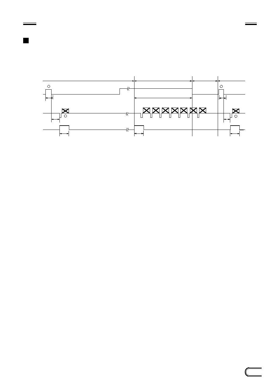
TIMING CHART OF EXTERNAL TRIGGER SHUTTER - MODE 1 (NON-RESET MODE)
For setting the shutter speed using DIP switch
HD/VD input
∑
Continuous HD/VD input
*
1: This is a signal input from the outside. The period of a continuous VD signal is prescribed as one field. Be
sure to input both HD and VD signals.
*
2: As shown in the table on page 7, exposure time Te is determined by the setting of a DIP switch.
*
3: The normal operation state is engaged when the high period exceeds 1/3 sec. After that, the external
trigger shutter operation is engaged when the trigger pulse goes "low". In this case, the area between the
falling edge of a trigger pulse and the subsequent 50 ms period is an external input inhibition area. During
the trigger inhibit period, an input trigger may be missed.
*
4: An image is output when an external VD signal falls 10 ms or more after a trigger pulse rises (shown by
2
and
3
in the figure). If the time (T in the figure) between the falling edges of a trigger pulse and external
VD signal is under 10 ms, an image is output when the external VD signal or the next external VD signal
falls (as shown by
1
in the figure). (In this case, an image is output when the next external VD signal falls.)
An image and WEN signal are always output together. For more details, refer to the WEN signal.
Note
: An image is superimposed when the next exposure ends before the previous image is output.
21
XC-ST50/50CE
XC-ST30/30CE
1/3 s or more
min. 10 ms
*
1
Trigger
Video out
WEN
*
1
External HD
*
1
External VD
(Single VD)
External trigger shutter operation
*
3 Normal operation
Mode transition state
External input
inhibition area
(50 ms)
External trigger
shutter operation
*
2 Exposure time Te
100
u
s to 250 ms
*
2 Exposure
time Te
*
4 T : T = 10 ms to 110 ms
250H
(XC-ST50/30)
293H
(XC-ST50CE/30CE)
250H
(XC-ST50/30)
293H
(XC-ST50CE/30CE)
1
3
1
2
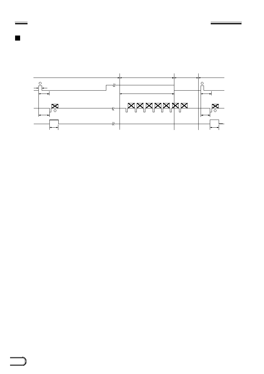
TIMING CHART OF EXTERNAL TRIGGER SHUTTER - MODE 1 (NON-RESET MODE)
For setting the shutter speed using DIP switch
HD/VD input
∑
Continuous HD input and single VD input
*
1: This is a signal input from the outside. Be sure to input both HD and VD signals. Make the phase of the VD
signal coincide with the falling edge of the HD signal.
*
2: As shown in the table on page 7, exposure time Te is determined by the setting of a DIP switch.
*
3: The normal operation state is engaged when the high period exceeds 1/3 sec. After that, the external
trigger shutter operation is engaged when the trigger pulse goes "low". In this case, the area between the
falling edge of a trigger pulse and the subsequent 50 ms period is an external input inhibition area. During
the trigger inhibit period, an input trigger may be missed.
*
4: Be sure to input an external VD signal for 10 ms to 110 ms from the rising edge of a trigger pulse (as shown
by
1
and
2
in the figure). For the input except described above, the operation cannot be ensured. If the
external VD signal is not input under the prescribed conditions, the normal operation is engaged several V
after a change in input operation under the prescribed conditions.
Note
: An image is superimposed when the next exposure ends before the previous image is output.
22
XC-ST50/50CE
XC-ST30/30CE
1/3 s or more
*
4
Interrnal VD
*
1
Trigger
Video out
WEN
External trigger shutter operation
*
3
Normal operation
Mode transition state
External input
inhibition area
(50 ms)
External trigger
shutter operation
*
2
Exposure time Te
100
u
s to 250 ms
*
2
Exposure time Te
*
2
Exposure
time Te
250H (XC-ST50/30)
293H (XC-ST50CE/30CE)
250H (XC-ST50/30)
293H (XC-ST50CE/30CE)
*
5
T : T = Under 10 ms
*
5
T : T = 10 ms or more
*
5
T : T = 10 ms or
more
1
2
3
1
2
3
TIMING CHART OF EXTERNAL TRIGGER SHUTTER - MODE 1 (NON-RESET MODE)
For setting the shutter speed using DIP switch
No HD/VD input (Internal synchronization)
*
1: This is a signal input from the outside.
*
2: As shown in the table on page 7, exposure time Te is determined by the setting of a DIP switch.
*
3: The normal operation state is engaged when the high period exceeds 1/3 sec. After that, the external
trigger shutter operation is engaged when the trigger pulse goes "low". In this case, the area between the
falling edge of a trigger pulse and the subsequent 50 ms period is an external input inhibition area. During
the trigger inhibit period, an input trigger may be missed.
*
4: An internal VD signal is output by setting the INT/EXT switch on the rear panel to INT.
*
5: An image is output when an internal VD signal falls 10 ms or more after a trigger pulse rises (as shown by
2
and
3
in the figure). If the time (T in the figure) between the falling edges of a trigger pulse and internal
VD signal is under 10 ms, an image is output when the internal VD signal or the nextinternal VD signal falls
(as shown by
1
in the figure). In this case, an image is output when the next internal VD signal falls. An
image and WEN signal are always output together. For more details, refer to the WEN signal. (The falling
edge of an internal VD signal is the same in phase as the beginning of an equalizing pulse in a SYNC V
area.)
Note
: An image is superimposed when the next exposure ends before the previous image is output.
23
XC-ST50/50CE
XC-ST30/30CE
1/3 s or more
External trigger shutter operation
*
3
Normal operation
Mode transition state
External input
inhibition area
(50 ms)
External trigger
shutter operation
*
1
Trigger
Video out
WEN
*
2
Exposure time Te
*
2
Exposure
time Te
250H
(XC-ST50/30)
293H
(XC-ST50CE/30CE)
250H
(XC-ST50/30)
293H
(XC-ST50CE/30CE)
*
4
1H to 2H
*
4
1H to 2H
1
3
1
3
250H
(XC-ST50/30)
293H
(XC-ST50CE/30CE)
*
5
TIMING CHART OF EXTERNAL TRIGGER SHUTTER - MODE 2
(RESET MODE)
For setting the shutter speed using TRG width
*
1: This is a signal input from the outside. The trigger interval should be trigger pulse width + 1 field + 2H
period or more. The trigger interval shorter than described above cannot be ensured. If a trigger pulse is
not input under the prescribed conditions, the normal operation is ensured several V after a change in
input operation under the prescribed conditions.
*
2: Exposure time Te
Te = Trigger width + 97
µ
s (XC-ST50/ST30),
Te = Trigger width + 120
µ
s (XC-ST50CE/ST30CE)
(The trigger width should be between 2
µ
s and 1/4 s)
*
3: The normal operation state is engaged when the high period exceeds 1/3 sec. After that, the external
trigger shutter operation is engaged when the trigger pulse goes "low". In this case, the area between the
falling edge of a trigger pulse and the subsequent 50 ms period is an external input inhibition area. During
the trigger inhibit period, an input trigger may be missed.
*
4: A VD signal is generated 1H to 2H after a trigger pulse falls, and an image is output in synchronization with
the VD signal.
*
5: When the external trigger shutter mode changes into the normal operation mode, a WEN signal is output.
24
XC-ST50/50CE
XC-ST30/30CE
1/3 s or more
External trigger shutter operation
100
u
s to 250 ms
*
3
Normal operation
Mode transition state
External input
inhibition area
(50 ms)
External trigger
shutter operation
*
2
Exposure time Te
*
4
T
*
4
T
*
2
Exposure
time Te
250H
(XC-ST50/ST30)
293H
(XC-ST50CE/ST30CE)
250H
(XC-ST50/ST30)
293H
XC-ST50CE/ST30CE)
1
3
1
3
*
1
Trigger
Video out
WEN
TIMING CHART OF EXTERNAL TRIGGER SHUTTER - MODE 2 (RESET MODE)
For setting the shutter speed using DIP switch
*
1: This is a signal input from the outside. The trigger interval should be shutter speed (DIP switch) + 1 field
+ 2H period or more. The trigger interval shorter than described above cannot be ensured. If a trigger
pulse is not input under the prescribed conditions, the normal operation is engaged several V after a
change in input operation under the prescribed conditions.
*
2: As shown in the table on page 7, exposure time Te is determined by the setting of a DIP switch.
*
3: The normal operation state is engaged when the high period exceeds 1/3 sec. After that, the external
trigger shutter operation is engaged when the trigger pulse goes "low". In this case, the area between the
falling edge of a trigger pulse and the subsequent 50 ms period is an external input inhibition area. During
the trigger inhibit period, an input trigger may be missed.
*
4: After a period set by a DIP switch from the rising edge of the trigger, an image is output.
25
XC-ST50/50CE
XC-ST30/30CE
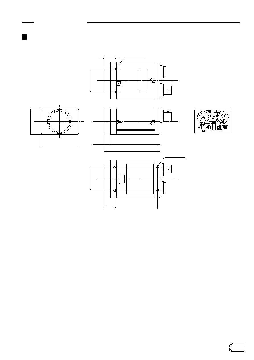
DIMENSIONS
XC-ST50/50CE
XC-ST30/30CE
(XC-ST50 model)
29
26
±
0.3
26
±
0.3
13
44
57.5
(8)
65.5
50
±
0.5
13
CCD
VIDEO CAMERA MODULE
XC-ST50
2-M3 deep 4
(Unit: mm)
4-M3 deep 4
26
XC-ST50/50CE
XC-ST30/30CE
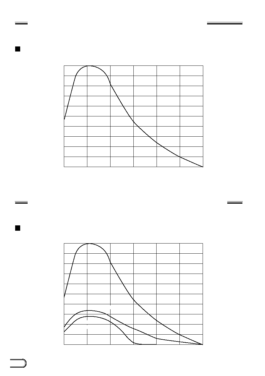
SPECTRAL RESPONSE CHARACTERISTICS
(TYPICAL VALUE)
XC-ST50/ST30
0.0
400
500
600
700
800
900
1000
0.1
0.2
0.3
0.4
0.5
0.6
0.7
0.8
Relativ
e sensitivity
Wavelength (nm)
0.9
1.0
COMPARISON OF SPECTRAL RESPONSE CHARACTERISTICS
(TYPICAL VALUE)
XC-75/73 and XC-ST50/ST30
0.0
400
500
600
700
800
900
1000
0.1
0.2
0.3
0.4
0.5
0.6
0.7
0.8
Relativ
e sensitivity
Wavelength (nm)
XC-ST50/30
0.9
1.0
XC-75/73
(without IR cut filter)
XC-75/73
(with IR cut filter)
27
XC-ST50/50CE
XC-ST30/30CE
VARIOUS LENS SELECTION
The following shows the various lens specifications of the accessories available.
XC-ST50/50CE and XC-ST30/30CE compatibility
Model name
VLC-08YM
8
1: 1.4
Manual
Manual
42.6∞
◊
32.6∞
32.6∞
◊
24.8∞
207
181
◊
132.8
181.3
◊
133.3
136.8
◊
100
137
◊
100.3
11.54
17.526
40
VLC-12YM
12
1: 1.8
Manual
Manual
29.6∞
◊
22.4∞
22.4∞
◊
16.9∞
208
125.2
◊
92.1
125.5
◊
92.5
94.7
◊
69.6
94.8
◊
69.6
10.99
17.526
40
VLC-16Y-M
16
1: 1.4
Manual
Manual
22.6∞
◊
17.0∞
17.0∞
◊
12.8∞
289
119.4
◊
88.5
119.6
◊
88.8
90
◊
66.8
90.4
◊
66.9
12.5
17.526
50
VLC-25Y-M
25
1: 1.6
Manual
Manual
14.6∞
◊
11.0∞
11.0∞
◊
8.2∞
204
52.1
◊
38.8
52.1
◊
38.9
39.4
◊
29.3
39.4
◊
29.3
11.6
17.526
42
VLC-50Y-M
50
1: 2.8
Manual
Manual
7.3∞
◊
5.5∞
5.5∞
◊
4.1∞
438
49.2
◊
37
49.7
◊
37.1
37.2
◊
27.9
37.5
◊
27.9
22.1
17.526
50
Operation
Field angle
(Horizontal x vertical)
MOD (mm)
Image pickup range during
maximum proximity
(horizontal
◊
vertical) (mm)
Back focus (mm)
Flange back (mm)
Mass (g)
Iris
Focus
1/2" CCD
1/3" CCD
XC-ST50
XC-ST50CE
XC-ST30
XC-ST30CE
MOD: Minimum object distance between the tip of the lens body and the object
List of C-Mount Lens
Focal distance (mm)
Maximum aperture ratio

XC-ST50/50CE
XC-ST30/30CE
Sony reserves the right to change specifications of the products and discontinue products without notice.
Technical information contained herein is for reference only and does not convey any license by any implication or otherwise
under any intellectual property right or other right of Sony or third parties.
Sony cannot assume responsibility for any right infringements arising out of the use of this information.
CCD B/W VIDEO
CAMERA MODULE
XC-ST50/50CE
XC-ST30/30CE
00A
© 1999 Sony Corporation. All rights reserved.
Reproduction in whole or in part without written permission is prohibited.
http://www.sony.co.jp/ISP/
Europe
http://www.pro.sony-europe.com/ISP
Sony Broadcast & Professional
HQ
15, rue Floreal 75831 Paris Cedex 17, France
Tel: +33-1-55-90-35-11
Fax: +33-1-55-90-35-17
Germany
Hugo-Eckener-Str. 20, 50829 Koln
Tel: +49-221-5966-322
Fax: +49-221-5966-491
France
15, rue Floreal 75831 Paris Cedex 17
Tel: +33-1-55-90-41-62
Fax: +33-1-55-90-13-57
UK
The Heights, Brooklands, Weybridge, Surrey KT13 0XW
Tel: +44-1932-816-340
Fax: +44-1932-817011
Nordic
Per Albin Hanssons vag 20 S-214 32 Malmo Sweden
Tel: +46-40-190-800
Fax : +46-40-190-450
Italy
Via Galileo Galilei 40 I-20092 Cinisello Balsamo, Milano
Tel: +39-02-618-38-431
Fax : +39-02-618-38-402
Sales Office :
Japan
http://www.sony.co.jp/ISP/
Sony Corporation
4-14-1 Asahi-cho,Atsugi-shi, Kanagawa,243-0014 Japan
Tel: +81-46-227-2346
Fax: +81-46-227-2347
Tel: +81-46-230-5873
Fax: +81-46-230-6243
USA
http://www.sony.com/professional
Sony Electronics Inc.
HQ
1 Sony Drive Park Ridge, NJ 07656
Tel: +1-800-686-7669
Canada
Sony of Canada Ltd.
115 Gordon Baker Rd, Toronto, Ontario M2H 3R6
Tel: +1-416-499-1414
Fax: +1-416-497-1774