SHANGHAI SUNRISE ELECTRONICS CO., LTD.
VOLTAGE: 50 TO 1000V CURRENT: 1.0A
FEATURES
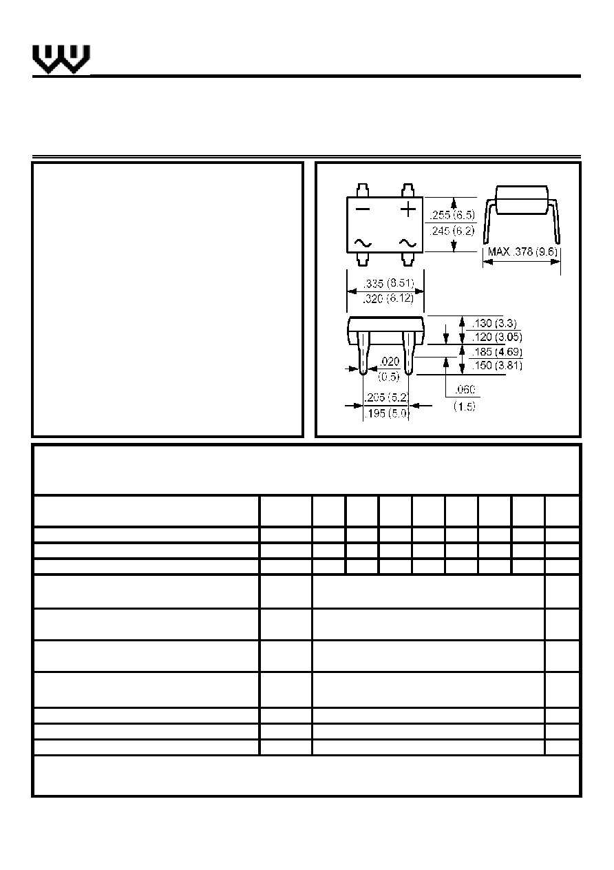
∑ Ideal for printed circuit board
∑ Reliable low cost construction utilizing
molded plastic technique
∑ Surge overload rating: 50 A peak
∑ High temperature soldering guaranteed:
250
o
C/10sec/ at terminals
MECHANICAL DATA
∑ Terminal: Plated leads solderable per
MIL-STD 202E, method 208C
∑ Case: UL-94 Class V-O recognized flame
retardant epoxy
∑ Polarity: Polarity symbol marked on body
∑ Mounting position: Any
MAXIMUM RATINGS AND ELECTRICAL CHARACTERISTICS
SYMBOL
DF
005
DF
01
DF
02
DF
04
DF
06
DF
08
DF
10
UNITS
Maximum Repetitive Peak Reverse Voltage
V
RRM
50
100
200
400
600
800
1000
V
Maximum RMS Voltage
V
RMS
35
70
140
280
420
560
700
V
Maximum DC Blocking Voltage
V
DC
50
100
200
400
600
800
1000
V
Maximum Average Forward Rectified Current
(T
a
=40
o
C)
Peak Forward Surge Current (8.3ms single
half sine-wave superimposed on rated load)
Maximum Instantaneous Forward Voltage
(at forward current 1.0A)
Maximum DC Reverse Current
T
a
=25
o
C
µ
A
(at rated DC blocking voltage)
T
a
=125
o
C
µ
A
Typical Junction capacitance
(Note 1)
C
J
pF
Typical Thermal Resistance
(Note 2)
R
(Ja)
o
C/W
Storage and Operating Junction Temperature
T
STG
,T
J
o
C
Note:
1. Measured at 1.0 MHz and applied voltage of 4.0 V
dc
2. Thermal Resistance from junction to Ambient mounted on P.C. Board with 13◊13mm copper pads.
http://www.sse-diode.com
DF005 THRU DF10
I
F(AV)
1.0
A
RATINGS
(Single-phase, half-wave, 60Hz, resistive or inductive load rating at 25
o
C, unless otherwise stated, for capacitive load,
derate current by 20%)
PASSIVATED BRIDGE RECTIFIER
SINGLE PHASE GLASS
A
40
-55 to +150
I
R
10.0
500
I
FSM
50
V
25
1.1
V
F
TECHNICAL
SPECIFICATION
DF
Dimensions in inches and (millimeters)