
©2001 Silicon Storage Technology, Inc.
S71125-03-000
9/01
375
1
The SST logo and SuperFlash are registered trademarks of Silicon Storage Technology, Inc.
SST is an authorized licensee of the CompactFlashTM and CF[logo]TM trademarks. Some data and tables are reproduced from the
CompactFlash Specification by permission of the CompactFlash Association. These specifications are subject to change without notice.
Data Sheet
FEATURES:
∑
CompactFlash Association specification
standard
∑
8, 16, 24, 32, 48, 64, 96, 128, 192, and 256 MByte
capacities
∑
Small Form Factor: 36.4 mm x 42.8 mm x 3.3 mm
∑
Supports 5.0-Volt and 3.3-Volt Read and Write
≠ 4.5-5.5V, 3.135-3.465V for commercial
∑
PC Card ATA and True IDE interface
≠ 512 Bytes sector
≠ ATA command set compatible
∑
Low Power Consumption:
≠ Active mode: 35 mA/55 mA (3.3V/5.0V)(typical)
≠ Sleep mode: 100 µA/150 µA (3.3V/5.0V)(typical)
∑
Data Transfer Rate to/from Host
≠ 20 MB/s burst at 5.0V
≠ 6.6 MB/s burst at 3.3V
∑
High Performance
≠ Up to 1.4 MB/sec sustained write transfer rate
(host to flash)
∑
Controller Overhead Command to DRQ
≠ Less than 0.5 ms
∑
Zero Data Retention Power
≠ Batteries not required for data storage
∑
Start Up Time
≠ Sleep to Read: 200 ns
≠ Sleep to Write: 200 ns
≠ Reset to Ready: 50 ms typical, 400 ms Max.
∑
Support for Commercial Temperature Range
≠ 0∞C to +70∞C for operating commercial
≠ -25∞C to +85∞C non-operating (storage)
∑
Extremely Rugged and Reliable
≠ Built-in ECC support corrects 3 random Bytes
error per 512 Byte sector
≠ 2000 G operating and non-operating shock
∑
Intelligent ATA/IDE Controller
≠ Built-in microcontroller with intelligent firmware
≠ 256 Bytes of attribute memory for storing CIS
information
≠ Supports multiple-sector Read/Write operation
to enhance system performance
∑
Power Management Unit
≠ Immediate disabling of unused circuitry
PRODUCT DESCRIPTION
SST's CompactFlash (CF) card is an ultra-small, low cost,
high performance, removable flash memory data storage
system. This technology is well suited for solid state mass
storage portable applications offering new and expanded
functionality while enabling smaller and lighter designs.
CompactFlash technology is widely used in a variety of
consumer products such as portable computers, digital
cameras, handheld data collection scanners, Personal
Digital Assistants (PDAs), handy terminals, audio players,
monitoring devices and set-top boxes.
SST's CompactFlash products provide complete PCMCIA-
ATA functionality and compatibility. This is achieved
because the 50-pin CF card can be easily slipped into a
passive 68-pin Type II adapter card that fully meets PCM-
CIA electrical and mechanical interface specifications.
SST's CompactFlash products are also fully compliant with
CFA standards. The SST CF card is read and written to
using a single power supply of 5.0V or 3.3V and is available
in 8 to 256 MByte densities.
SST's CompactFlash cards contain additional attribute
memory of 256 Bytes for storing the Card Information
Structure (CIS) information. SST's CompactFlash card has
built in microcontroller and file management firmware that
communicates with ATA standard interfaces; therefore, the
SST's CompactFlash cards do not require additional soft-
ware for the host, such as Flash File System (FFS) and
Memory Technology Driver (MTD).
CompactFlash Card
SST48CF008 / 016 / 024 / 032 / 048 / 064 / 096 / 128 / 192 / 256
SST48CFxxxATA/IDE Standard CompactFlash Card
8MB / 16MB / 24MB / 32MB / 48MB / 64MB / 96MB / 128MB / 192MB / 256MB

2
Data Sheet
CompactFlash Card
SST48CF008 / 016 / 024 / 032 / 048 / 064 / 096 / 128 / 192 / 256
©2001 Silicon Storage Technology, Inc.
S71125-03-000
9/01
375
TABLE OF CONTENTS
PRODUCT DESCRIPTION . . . . . . . . . . . . . . . . . . . . . . . . . . . . . . . . . . . . . . . . . . . . . . . . . . . . . . . . . . . . . . . . . . . 1
1.0 GENERAL DESCRIPTION . . . . . . . . . . . . . . . . . . . . . . . . . . . . . . . . . . . . . . . . . . . . . . . . . . . . . . . . . . . . . . . 5
1.1 Performance-optimized ATA Controller . . . . . . . . . . . . . . . . . . . . . . . . . . . . . . . . . . . . . . . . . . . . . . . . . . 5
1.1.1 Microcontroller Unit (MCU). . . . . . . . . . . . . . . . . . . . . . . . . . . . . . . . . . . . . . . . . . . . . . . . . . . . . . . 5
1.1.2 Internal Direct Memory Access (DMA) Control . . . . . . . . . . . . . . . . . . . . . . . . . . . . . . . . . . . . . . . 5
1.1.3 Power Management Unit (PMU) . . . . . . . . . . . . . . . . . . . . . . . . . . . . . . . . . . . . . . . . . . . . . . . . . . 5
1.1.4 SRAM Buffer . . . . . . . . . . . . . . . . . . . . . . . . . . . . . . . . . . . . . . . . . . . . . . . . . . . . . . . . . . . . . . . . . 5
1.1.5 Embedded Flash File System . . . . . . . . . . . . . . . . . . . . . . . . . . . . . . . . . . . . . . . . . . . . . . . . . . . . 5
1.1.6 Error Correction Code (ECC) . . . . . . . . . . . . . . . . . . . . . . . . . . . . . . . . . . . . . . . . . . . . . . . . . . . . . 5
1.2 SST's CompactFlash Card Product Offering . . . . . . . . . . . . . . . . . . . . . . . . . . . . . . . . . . . . . . . . . . . . . . 6
2.0 ELECTRICAL INTERFACE . . . . . . . . . . . . . . . . . . . . . . . . . . . . . . . . . . . . . . . . . . . . . . . . . . . . . . . . . . . . . . 6
2.0.1 Pin Assignment and Pin Type . . . . . . . . . . . . . . . . . . . . . . . . . . . . . . . . . . . . . . . . . . . . . . . . . . . . 6
2.1 Electrical Description . . . . . . . . . . . . . . . . . . . . . . . . . . . . . . . . . . . . . . . . . . . . . . . . . . . . . . . . . . . . . . . . 6
2.2 Card Pin Assignment . . . . . . . . . . . . . . . . . . . . . . . . . . . . . . . . . . . . . . . . . . . . . . . . . . . . . . . . . . . . . . . . 7
2.3 Electrical Specification . . . . . . . . . . . . . . . . . . . . . . . . . . . . . . . . . . . . . . . . . . . . . . . . . . . . . . . . . . . . . . 13
2.3.1 Input Leakage Current . . . . . . . . . . . . . . . . . . . . . . . . . . . . . . . . . . . . . . . . . . . . . . . . . . . . . . . . . 13
2.3.2 Input Characteristics. . . . . . . . . . . . . . . . . . . . . . . . . . . . . . . . . . . . . . . . . . . . . . . . . . . . . . . . . . . 14
2.3.3 Output Drive Type . . . . . . . . . . . . . . . . . . . . . . . . . . . . . . . . . . . . . . . . . . . . . . . . . . . . . . . . . . . . 14
2.3.4 Output Drive Characteristics . . . . . . . . . . . . . . . . . . . . . . . . . . . . . . . . . . . . . . . . . . . . . . . . . . . . 14
2.3.5 Interface/Bus Timing . . . . . . . . . . . . . . . . . . . . . . . . . . . . . . . . . . . . . . . . . . . . . . . . . . . . . . . . . . 14
2.3.6 Attribute Memory Read Timing Specification . . . . . . . . . . . . . . . . . . . . . . . . . . . . . . . . . . . . . . . . 15
2.3.7 Configuration Register (Attribute Memory) Write Timing specification. . . . . . . . . . . . . . . . . . . . . 16
2.3.8 Common Memory Read Timing Specification . . . . . . . . . . . . . . . . . . . . . . . . . . . . . . . . . . . . . . . 17
2.3.9 Common Memory Write Timing Specification . . . . . . . . . . . . . . . . . . . . . . . . . . . . . . . . . . . . . . . 18
2.3.10 I/O Input (Read) Timing Specification . . . . . . . . . . . . . . . . . . . . . . . . . . . . . . . . . . . . . . . . . . . . 19
2.3.11 I/O Output (Write) Timing Specification . . . . . . . . . . . . . . . . . . . . . . . . . . . . . . . . . . . . . . . . . . . 20
2.3.12 True IDE Mode I/O Input (Read) Timing Specification . . . . . . . . . . . . . . . . . . . . . . . . . . . . . . . . 21
2.3.13 True IDE Mode I/O Output (Write) Timing Specification . . . . . . . . . . . . . . . . . . . . . . . . . . . . . . 22
2.4 Card Configuration . . . . . . . . . . . . . . . . . . . . . . . . . . . . . . . . . . . . . . . . . . . . . . . . . . . . . . . . . . . . . . . . . 23
2.4.1 Attribute Memory Function . . . . . . . . . . . . . . . . . . . . . . . . . . . . . . . . . . . . . . . . . . . . . . . . . . . . . . 24
2.4.2 Configuration Option Register (Address 200H in Attribute Memory) . . . . . . . . . . . . . . . . . . . . . . 24
2.4.3 Card Configuration and Status Register (Address 202H in Attribute Memory) . . . . . . . . . . . . . . 25
2.4.4 Pin Replacement Register (Address 204H in Attribute Memory) . . . . . . . . . . . . . . . . . . . . . . . . . 26
2.4.5 Socket and Copy Register (Address 206H in Attribute Memory) . . . . . . . . . . . . . . . . . . . . . . . . . 26
2.5 I/O Transfer Function . . . . . . . . . . . . . . . . . . . . . . . . . . . . . . . . . . . . . . . . . . . . . . . . . . . . . . . . . . . . . . . 27
2.5.1 I/O Function . . . . . . . . . . . . . . . . . . . . . . . . . . . . . . . . . . . . . . . . . . . . . . . . . . . . . . . . . . . . . . . . . 27
2.6 Common Memory Transfer Function . . . . . . . . . . . . . . . . . . . . . . . . . . . . . . . . . . . . . . . . . . . . . . . . . . . 28
2.6.1 Common Memory Function . . . . . . . . . . . . . . . . . . . . . . . . . . . . . . . . . . . . . . . . . . . . . . . . . . . . . 28
2.7 True IDE Mode I/O Transfer Function . . . . . . . . . . . . . . . . . . . . . . . . . . . . . . . . . . . . . . . . . . . . . . . . . . 29
2.7.1 True IDE Mode I/O Function . . . . . . . . . . . . . . . . . . . . . . . . . . . . . . . . . . . . . . . . . . . . . . . . . . . . 29

Data Sheet
CompactFlash Card
SST48CF008 / 016 / 024 / 032 / 048 / 064 / 096 / 128 / 192 / 256
3
©2001 Silicon Storage Technology, Inc.
S71125-03-000
9/01
375
3.0 SOFTWARE INTERFACE . . . . . . . . . . . . . . . . . . . . . . . . . . . . . . . . . . . . . . . . . . . . . . . . . . . . . . . . . . . . . . 30
3.1 CF-ATA Drive Register Set Definition and Protocol. . . . . . . . . . . . . . . . . . . . . . . . . . . . . . . . . . . . . . . . 30
3.1.1 I/O Primary and Secondary Address Configurations . . . . . . . . . . . . . . . . . . . . . . . . . . . . . . . . . . 30
3.1.2 Contiguous I/O Mapped Addressing . . . . . . . . . . . . . . . . . . . . . . . . . . . . . . . . . . . . . . . . . . . . . . 31
3.1.3 Memory Mapped Addressing . . . . . . . . . . . . . . . . . . . . . . . . . . . . . . . . . . . . . . . . . . . . . . . . . . . . 32
3.1.4 True IDE Mode Addressing . . . . . . . . . . . . . . . . . . . . . . . . . . . . . . . . . . . . . . . . . . . . . . . . . . . . . 33
3.1.5 CF-ATA Registers . . . . . . . . . . . . . . . . . . . . . . . . . . . . . . . . . . . . . . . . . . . . . . . . . . . . . . . . . . . . 33
3.1.5.1 Data Register . . . . . . . . . . . . . . . . . . . . . . . . . . . . . . . . . . . . . . . . . . . . . . . . . . . . . . . . . 33
3.1.5.2 Error Register . . . . . . . . . . . . . . . . . . . . . . . . . . . . . . . . . . . . . . . . . . . . . . . . . . . . . . . . . 34
3.1.5.3 Feature Register . . . . . . . . . . . . . . . . . . . . . . . . . . . . . . . . . . . . . . . . . . . . . . . . . . . . . . . 34
3.1.5.4 Sector Count Register . . . . . . . . . . . . . . . . . . . . . . . . . . . . . . . . . . . . . . . . . . . . . . . . . . . 34
3.1.5.5 Sector Number (LBA 7-0) Register . . . . . . . . . . . . . . . . . . . . . . . . . . . . . . . . . . . . . . . . . 34
3.1.5.6 Cylinder Low (LBA 15-8) Register. . . . . . . . . . . . . . . . . . . . . . . . . . . . . . . . . . . . . . . . . . 34
3.1.5.7 Cylinder High (LBA 23-16) Register . . . . . . . . . . . . . . . . . . . . . . . . . . . . . . . . . . . . . . . . 34
3.1.5.8 Drive/Head (LBA 27-24) Register . . . . . . . . . . . . . . . . . . . . . . . . . . . . . . . . . . . . . . . . . . 35
3.1.5.9 Status & Alternate Status Registers . . . . . . . . . . . . . . . . . . . . . . . . . . . . . . . . . . . . . . . . 36
3.1.5.10 Device Control Register . . . . . . . . . . . . . . . . . . . . . . . . . . . . . . . . . . . . . . . . . . . . . . . . 36
3.1.5.11 Card (Drive) Address Register . . . . . . . . . . . . . . . . . . . . . . . . . . . . . . . . . . . . . . . . . . . 37
3.2 CF-ATA Command Description . . . . . . . . . . . . . . . . . . . . . . . . . . . . . . . . . . . . . . . . . . . . . . . . . . . . . . . 37
3.2.1 CF-ATA Command Set . . . . . . . . . . . . . . . . . . . . . . . . . . . . . . . . . . . . . . . . . . . . . . . . . . . . . . . . 37
3.2.1.1 Check Power Mode - 98H or E5H . . . . . . . . . . . . . . . . . . . . . . . . . . . . . . . . . . . . . . . . . . 39
3.2.1.2 Execute Drive Diagnostic - 90H . . . . . . . . . . . . . . . . . . . . . . . . . . . . . . . . . . . . . . . . . . . 39
3.2.1.3 Erase Sector(s) - C0H . . . . . . . . . . . . . . . . . . . . . . . . . . . . . . . . . . . . . . . . . . . . . . . . . . . 40
3.2.1.4 Format Track - 50H . . . . . . . . . . . . . . . . . . . . . . . . . . . . . . . . . . . . . . . . . . . . . . . . . . . . . 40
3.2.1.5 Identify Drive - ECH. . . . . . . . . . . . . . . . . . . . . . . . . . . . . . . . . . . . . . . . . . . . . . . . . . . . . 40
3.2.1.5.1 General Configuration. . . . . . . . . . . . . . . . . . . . . . . . . . . . . . . . . . . . . . . . . . . . 42
3.2.1.5.2 Default Number of Cylinders. . . . . . . . . . . . . . . . . . . . . . . . . . . . . . . . . . . . . . . 42
3.2.1.5.3 Default Number of Heads . . . . . . . . . . . . . . . . . . . . . . . . . . . . . . . . . . . . . . . . . 42
3.2.1.5.4 Number of Unformatted Bytes per Track . . . . . . . . . . . . . . . . . . . . . . . . . . . . . 42
3.2.1.5.5 Number of Unformatted Bytes per Sector. . . . . . . . . . . . . . . . . . . . . . . . . . . . . 42
3.2.1.5.6 Default Number of Sectors per Track . . . . . . . . . . . . . . . . . . . . . . . . . . . . . . . . 42
3.2.1.5.7 Number of Sectors per Card. . . . . . . . . . . . . . . . . . . . . . . . . . . . . . . . . . . . . . . 42
3.2.1.5.8 Memory Card Serial Number . . . . . . . . . . . . . . . . . . . . . . . . . . . . . . . . . . . . . . 42
3.2.1.5.9 Buffer Type . . . . . . . . . . . . . . . . . . . . . . . . . . . . . . . . . . . . . . . . . . . . . . . . . . . . 42
3.2.1.5.10 Buffer Size . . . . . . . . . . . . . . . . . . . . . . . . . . . . . . . . . . . . . . . . . . . . . . . . . . . 42
3.2.1.5.11 ECC Count . . . . . . . . . . . . . . . . . . . . . . . . . . . . . . . . . . . . . . . . . . . . . . . . . . . 42
3.2.1.5.12 Firmware Revision . . . . . . . . . . . . . . . . . . . . . . . . . . . . . . . . . . . . . . . . . . . . . 42
3.2.1.5.13 Model Number . . . . . . . . . . . . . . . . . . . . . . . . . . . . . . . . . . . . . . . . . . . . . . . . 42
3.2.1.5.14 Read/Write Multiple Sector Count . . . . . . . . . . . . . . . . . . . . . . . . . . . . . . . . . 42
3.2.1.5.15 Capabilities . . . . . . . . . . . . . . . . . . . . . . . . . . . . . . . . . . . . . . . . . . . . . . . . . . . 43
3.2.1.5.16 PIO Data Transfer Cycle Timing Mode. . . . . . . . . . . . . . . . . . . . . . . . . . . . . . 43
3.2.1.5.17 Translation Parameters Valid . . . . . . . . . . . . . . . . . . . . . . . . . . . . . . . . . . . . . 43
3.2.1.5.18 Current Number of Cylinders, Heads, Sectors/Track . . . . . . . . . . . . . . . . . . . 43
3.2.1.5.19 Current Capacity. . . . . . . . . . . . . . . . . . . . . . . . . . . . . . . . . . . . . . . . . . . . . . . 43
3.2.1.5.20 Multiple Sector Setting . . . . . . . . . . . . . . . . . . . . . . . . . . . . . . . . . . . . . . . . . . 43
3.2.1.5.21 Advanced PIO Data Transfer Mode . . . . . . . . . . . . . . . . . . . . . . . . . . . . . . . . 43
3.2.1.5.22 Minimum PIO Transfer Cycle Time Without Flow Control . . . . . . . . . . . . . . . 43
3.2.1.5.23 Minimum PIO Transfer Cycle Time With IORDY . . . . . . . . . . . . . . . . . . . . . . 43
3.2.1.5.24 Total Sectors Addressable in LBA Mode . . . . . . . . . . . . . . . . . . . . . . . . . . . . 43
3.2.1.6 Idle - 97H or E3H. . . . . . . . . . . . . . . . . . . . . . . . . . . . . . . . . . . . . . . . . . . . . . . . . . . . . . . 44
3.2.1.7 Idle Immediate - 95H or E1H. . . . . . . . . . . . . . . . . . . . . . . . . . . . . . . . . . . . . . . . . . . . . . 44

4
Data Sheet
CompactFlash Card
SST48CF008 / 016 / 024 / 032 / 048 / 064 / 096 / 128 / 192 / 256
©2001 Silicon Storage Technology, Inc.
S71125-03-000
9/01
375
3.2.1.8 Initialize Drive Parameters - 91H. . . . . . . . . . . . . . . . . . . . . . . . . . . . . . . . . . . . . . . . . . . 44
3.2.1.9 Read Buffer - E4H . . . . . . . . . . . . . . . . . . . . . . . . . . . . . . . . . . . . . . . . . . . . . . . . . . . . . . 45
3.2.1.10 Read Multiple - C4H . . . . . . . . . . . . . . . . . . . . . . . . . . . . . . . . . . . . . . . . . . . . . . . . . . . 45
3.2.1.11 Read Long Sector - 22H or 23H . . . . . . . . . . . . . . . . . . . . . . . . . . . . . . . . . . . . . . . . . . 46
3.2.1.12 Read Sector(s) - 20H or 21H. . . . . . . . . . . . . . . . . . . . . . . . . . . . . . . . . . . . . . . . . . . . . 46
3.2.1.13 Read Verify Sector(s) - 40H or 41H . . . . . . . . . . . . . . . . . . . . . . . . . . . . . . . . . . . . . . . 47
3.2.1.14 Recalibrate - 1XH . . . . . . . . . . . . . . . . . . . . . . . . . . . . . . . . . . . . . . . . . . . . . . . . . . . . . 47
3.2.1.15 Request Sense - 03H . . . . . . . . . . . . . . . . . . . . . . . . . . . . . . . . . . . . . . . . . . . . . . . . . . 47
3.2.1.16 Seek - 7XH . . . . . . . . . . . . . . . . . . . . . . . . . . . . . . . . . . . . . . . . . . . . . . . . . . . . . . . . . . 48
3.2.1.17 Set Features - EFH . . . . . . . . . . . . . . . . . . . . . . . . . . . . . . . . . . . . . . . . . . . . . . . . . . . . 48
3.2.1.18 Set Multiple Mode - C6H . . . . . . . . . . . . . . . . . . . . . . . . . . . . . . . . . . . . . . . . . . . . . . . . 49
3.2.1.19 Set Sleep Mode- 99H or E6H . . . . . . . . . . . . . . . . . . . . . . . . . . . . . . . . . . . . . . . . . . . . 50
3.2.1.20 Standby - 96H or E2H . . . . . . . . . . . . . . . . . . . . . . . . . . . . . . . . . . . . . . . . . . . . . . . . . . 50
3.2.1.21 Standby Immediate - 94H or E0H . . . . . . . . . . . . . . . . . . . . . . . . . . . . . . . . . . . . . . . . . 50
3.2.1.22 Translate Sector - 87H . . . . . . . . . . . . . . . . . . . . . . . . . . . . . . . . . . . . . . . . . . . . . . . . . 51
3.2.1.23 Wear Level - F5H . . . . . . . . . . . . . . . . . . . . . . . . . . . . . . . . . . . . . . . . . . . . . . . . . . . . . 51
3.2.1.24 Write Buffer - E8H . . . . . . . . . . . . . . . . . . . . . . . . . . . . . . . . . . . . . . . . . . . . . . . . . . . . . 52
3.2.1.25 Write Long Sector - 32H or 33H . . . . . . . . . . . . . . . . . . . . . . . . . . . . . . . . . . . . . . . . . . 52
3.2.1.26 Write Multiple Command - C5H. . . . . . . . . . . . . . . . . . . . . . . . . . . . . . . . . . . . . . . . . . . 53
3.2.1.27 Write Multiple without Erase - CDH. . . . . . . . . . . . . . . . . . . . . . . . . . . . . . . . . . . . . . . . 54
3.2.1.28 Write Sector(s) - 30H or 31H. . . . . . . . . . . . . . . . . . . . . . . . . . . . . . . . . . . . . . . . . . . . . 54
3.2.1.29 Write Sector(s) without Erase - 38H . . . . . . . . . . . . . . . . . . . . . . . . . . . . . . . . . . . . . . . 55
3.2.1.30 Write Verify - 3CH . . . . . . . . . . . . . . . . . . . . . . . . . . . . . . . . . . . . . . . . . . . . . . . . . . . . . 55
3.2.2 Error Posting . . . . . . . . . . . . . . . . . . . . . . . . . . . . . . . . . . . . . . . . . . . . . . . . . . . . . . . . . . . . . . . . 56
4.0 APPENDIX . . . . . . . . . . . . . . . . . . . . . . . . . . . . . . . . . . . . . . . . . . . . . . . . . . . . . . . . . . . . . . . . . . . . . . . . . . 57
4.1 Differences between CF-ATA and PC Card-ATA/True IDE . . . . . . . . . . . . . . . . . . . . . . . . . . . . . . . . . . 57
4.1.1 Electrical Differences . . . . . . . . . . . . . . . . . . . . . . . . . . . . . . . . . . . . . . . . . . . . . . . . . . . . . . . . . . 57
4.1.1.1 TTL Compatibility . . . . . . . . . . . . . . . . . . . . . . . . . . . . . . . . . . . . . . . . . . . . . . . . . . . . . . 57
4.1.1.2 Pull Up Resistor Input Leakage Current . . . . . . . . . . . . . . . . . . . . . . . . . . . . . . . . . . . . . 57
4.1.2 Functional Differences . . . . . . . . . . . . . . . . . . . . . . . . . . . . . . . . . . . . . . . . . . . . . . . . . . . . . . . . . 57
4.1.2.1 Additional Set Features Codes in CF-ATA . . . . . . . . . . . . . . . . . . . . . . . . . . . . . . . . . . . 57
4.1.2.2 Additional Commands in CF-ATA . . . . . . . . . . . . . . . . . . . . . . . . . . . . . . . . . . . . . . . . . . 57
4.1.2.3 Idle Timer . . . . . . . . . . . . . . . . . . . . . . . . . . . . . . . . . . . . . . . . . . . . . . . . . . . . . . . . . . . . 57
4.1.2.4 Recovery from Sleep Mode. . . . . . . . . . . . . . . . . . . . . . . . . . . . . . . . . . . . . . . . . . . . . . . 57
5.0 PHYSICAL DIMENSIONS . . . . . . . . . . . . . . . . . . . . . . . . . . . . . . . . . . . . . . . . . . . . . . . . . . . . . . . . . . . . . . 58
6.0 PRODUCT ORDERING INFORMATION . . . . . . . . . . . . . . . . . . . . . . . . . . . . . . . . . . . . . . . . . . . . . . . . . . . 59
6.1 Valid combinations . . . . . . . . . . . . . . . . . . . . . . . . . . . . . . . . . . . . . . . . . . . . . . . . . . . . . . . . . . . . . . . . . 59
7.0 LIMITED WARRANTY . . . . . . . . . . . . . . . . . . . . . . . . . . . . . . . . . . . . . . . . . . . . . . . . . . . . . . . . . . . . . . . . . 60
7.1 Life Support Policy . . . . . . . . . . . . . . . . . . . . . . . . . . . . . . . . . . . . . . . . . . . . . . . . . . . . . . . . . . . . . . . . . 60
8.0 PATENT PROTECTION . . . . . . . . . . . . . . . . . . . . . . . . . . . . . . . . . . . . . . . . . . . . . . . . . . . . . . . . . . . . . . . . 60
9.0 PCMCIA STANDARD . . . . . . . . . . . . . . . . . . . . . . . . . . . . . . . . . . . . . . . . . . . . . . . . . . . . . . . . . . . . . . . . . . 60
10.0 COMPACTFLASH SPECIFICATION . . . . . . . . . . . . . . . . . . . . . . . . . . . . . . . . . . . . . . . . . . . . . . . . . . . . . . 60
11.0 RELATED DOCUMENTS . . . . . . . . . . . . . . . . . . . . . . . . . . . . . . . . . . . . . . . . . . . . . . . . . . . . . . . . . . . . . . . 60
Data Sheet
CompactFlash Card
SST48CF008 / 016 / 024 / 032 / 048 / 064 / 096 / 128 / 192 / 256
5
©2001 Silicon Storage Technology, Inc.
S71125-03-000
9/01
375
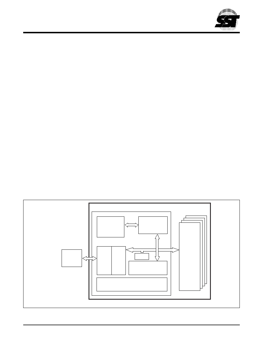
1.0 GENERAL DESCRIPTION
The SST's CompactFlash card contains a controller,
embedded firmware storage and flash media in a match-
book sized package with a 50-pin connector consisting of
two rows of 25 female contacts each on 50 mil (1.27 mm)
centers. Refer to Figure 1 for SST's CompactFlash card
block diagram. The controller interfaces with the host sys-
tem allowing data to be written to and read from the flash
media.
1.1 Performance-optimized ATA Controller
The heart of a CompactFlash card is the ATA controller
which translates standard IDE/ATA signals into flash media
data and controls. SST's CompactFlash card contains a
proprietary ATA controller that was specifically designed to
attain high data throughput from host to flash. The following
components contribute to the ATA controller's performance.
1.1.1 Microcontroller Unit (MCU)
The MCU translates IDE/ATA commands into data and
control signals required for flash memory operation.
1.1.2 Internal Direct Memory Access (DMA) Control
The ATA controller inside SST's CompactFlash card uses
DMA allowing instant data transfer to memory. This imple-
mentation eliminates controller overhead associated with
traditional, firmware based, memory control, increasing
data transfer rate.
1.1.3 Power Management Unit (PMU)
Power Management Unit controls the power consumption
of the CompactFlash card. The PMU dramatically extends
product battery life by putting the part of the circuitry that is
not in operation into sleep mode.
1.1.4 SRAM Buffer
A key contributor to the ATA controller performance is a
SRAM buffer. The buffer optimizes host's data writes to
flash media.
1.1.5 Embedded Flash File System
Embedded Flash File System is an integral part of the
SST's ATM controller. It contains MCU firmware that per-
forms the following tasks:
1. Translates host side signals into flash media
Writes and Reads.
2. Provides flash media wear leveling to spread the
flash writes across all the memory address space
to increase the longevity of flash media.
3. Keeps track of data file structures.
1.1.6 Error Correction Code (ECC)
The ATA Controller contains ECC algorithm that corrects
3 bytes of error per 512 Byte sector.
FIGURE 1: SST C
OMPACT
F
LASH
B
LOCK
D
IAGRAM
375 ILL1-1.4
Embedded
Flash
File System
MCU
ECC
To
Host
Internal
DMA
SRAM Buffer
ATA Controller
PMU
Flash
Media