 | –≠–ª–µ–∫—Ç—Ä–æ–Ω–Ω—ã–π –∫–æ–º–ø–æ–Ω–µ–Ω—Ç: NAA101 | –°–∫–∞—á–∞—Ç—å:  PDF PDF  ZIP ZIP |

1
TABLE OF CONTENTS
Description of Terminology.............................................................................................2
Structural Drawing ......................................................................................................2
Reliability Test and Measuring Method ...........................................................................2
Handling Precautions ...................................................................................................3
Super Bright LED Light Bar Module
Description of Part Number ....................................................................................4
Characteristics by Color ..........................................................................................4
LED Light Bar Module Product Line ........................................................................4-7
Super Bright LED Numeric Display (Seven Segment Display)
Description of Part Number ..........................................................................................8
Characteristics by Color .............................................................................................8
7.5mm Type ...............................................................................................................9
10.0mm Type .........................................................................................................10-12
15.0mm Type ............................................................................................................13
25.0mm Type ............................................................................................................14
Bi-Color LED Numeric Display.............................................................................................15
Alpha Numeric LED Display ..........................................................................................16
Index by Part Number .............................................................................................17-19
Absolute Max. Ratings
ITEMS
SYMBOLS
UNIT
DEFINITION
Power dissipation
Forward current
Peak forward current
Current derating
Forward voltage
Reverse current
Luminous intensity
Peak wavelength
Spectral line half width
Power dissipated by forward current and forward voltage
Current from anode to cathode
Forward peak current driven during pulse lighting
Derating over 25∞C ambient temperature
Voltage drop when forward current goes from anode to cathode
Leakage current when bias voltage is applied from cathode to anode
Flux in lumens per unit of solid angle on optical axis
Wavelength at which radiant intensity becomes greatest
Wavelength range in which radiant intensity becomes more than 50% of its peak value
(Pd)
(I
F
)
(I
FM
)
(
I
F
)
(V
F
)
(I
R
)
(I
V
)
(
p)
(
)
(mW)
(mA)
(mA)
(mA/∞C)
(V)
(
µ
A)
(mcd)
(nm)
(nm)
Electro-optical characteristics
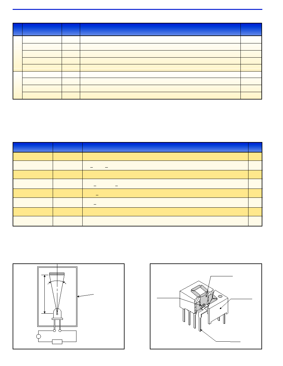
DESCRIPTION OF TERMINOLOGY
RELIABILITY TEST AND MEASURING METHOD
Items to be Guaranteed for LEDs
Measuring Method
Luminous Intensity (Iv)
TEST ITEM
STANDARDS
TEST CONDITION
SAMPLE
SIZE
Operating Endurance Test
Resistance to Soldering Heat
Temperature Cycling
Humidity (Steady State)
High Temperature (Storage)
Low Temperature (Storage)
Lead Tension
Vibration Fatigue
JIS C 7035
Added documents
JIS C 7021
A-1
JIS C 7021
A-4
JIS C 7021
B-11
JIS C 7021
B-10
JIS C 7021
A-12
JIS C 7021
A-11
JIS C 7021
A-10
Ta=25∞C, I
F
=Maximum Rated Current, t=1000 Hrs.
260+5∞C, 10+1sec., 3mm from package base
-30∞C (30 min) to normal temperature (15 min) to +100∞C (30 min) To normal temperature (15 min) 5 cycles
Ta=60+2∞C, RH=90+5%, t=1000Hr
Ta=100+2∞C, t=1000Hr
Ta=30+2∞C, t=1000Hr
*1kg/10 sec. one time (thin lead: 0.5kg)
10G, 100 to 2000Hz sweep for 20 min., 2 hours for directions X, Y and Z
25
25
25
25
25
25
10
10
Epoxy resin
LED chip
Lead frame
Lamp house
2
Structural Drawing for Numeric Display
LED
A
Dark room
Detector
7
∞
(0.01sr)
100mm
Constant Current Power Supply
3
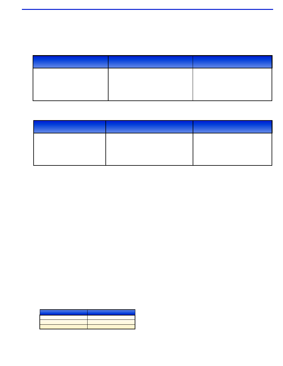
Soldering Conditions
Please refer to each product to see if it's compatible with lead-free soldering.
SOLDERING IRON
DIP SOLDERING
REFLOW SOLDERING
Iron Tip Temperature: 300∞C Max. (30W Max.)
Soldering Time: 3 Seconds Max.
Location: At least 3.0mm away from resin
Pre-heat: 80∞C Max. / 60 sec. Max.
(Resin surface temperature)
Bath Temperature: 260∞C Max.
Dipping Time: 5 sec. Max.
Position: At least 3.0mm away from resin body
Not recommended
Residual solder of flux left on the LED housing could reduce intensity
and could affect the optical characteristics. Excess flux can be
removed by the following chemical method:
1. Cleaning solvents (dipping time: 3 minutes maximum at
normal temperature)
∑ Ethyl alcohol
∑ Isopropyl alcohol
∑ Pure water (after cleaning, the water must be removed
by drying)
∑ Drying condition: 90∞C max., 30 sec. max. and 4 times max.
2. The effect of ultrasonic cleaning on the LED resin body depends
on such factors as the oscillator output, size of PCB and LED
mounting method. Ultrasonic cleaning is strongly recommended
after confirming that there are no problems.
1. Ultrasonic wave frequency: 28 kHz or 40 kHz
2. Output: 20 W/I
3. The solvent for freon equivalent (recommended after confirming
that there are no problems).
∑ AK-225AES
∑ Clean through
∑ Pine alpha ST-100S
Cleaning
Chemicals
Freon substitute detergent
Ethyl alcohol
Isopropyl alcohol
Pure water
AK225AES
Clean through 705H
Pine alpha ST-100S
HANDLING PRECAUTIONS
*
DIP Soldering and cleaning is not recommended for Alpha-Numeric (AAR121and AAA121) LED displays.
Lead-Free Soldering Conditions
Conventional Soldering Conditions
SOLDERING IRON
DIP SOLDERING
REFLOW SOLDERING
Iron Tip Temperature: 400∞C Max.
Soldering Iron: 30W Max.
Soldering Time: 3 Seconds Max.
Position: At least 2.0mm away from resin
Pre-heat: 100∞C Max. / 60 seconds Max.
(Resin surface temperature)
Bath Temperature: 265∞C Max.
Dipping time: 5 sec. Max.
Position: At least 2.0mm away from resin body
Not recommended
4
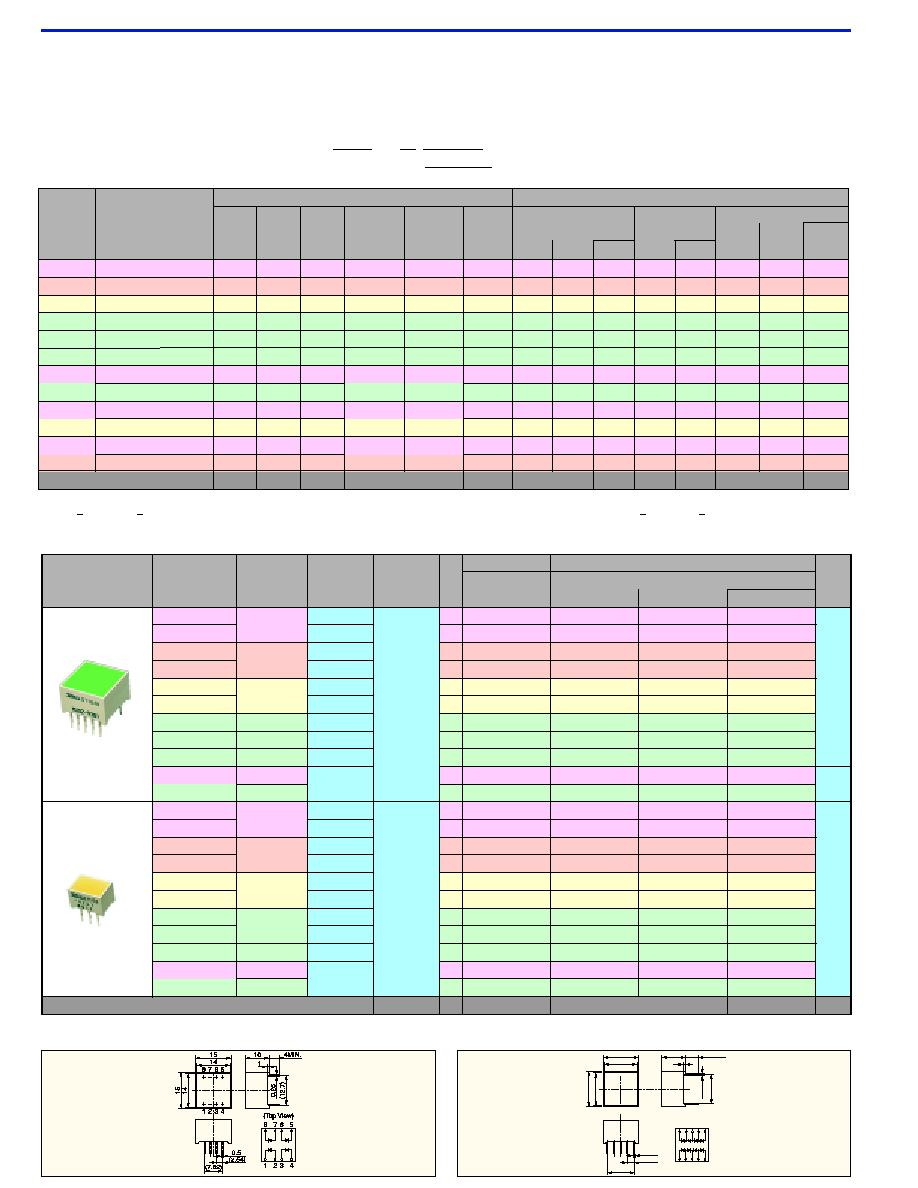
SUPER BRIGHT LED LIGHT BAR MODULE
Description of Part Number
Stanley's MU series of super-bright LED light bar modules can be selected from a wide variety of configurations and colors to suit a broad range of
requirements. By using front mask patterns, including letters, numbers and even graphics, this series is usable for a myriad of display applications.
MU 0 2 - 2 2 0 1
Shape
Code
Emitted
color
Suffix
2.Red 3.Orange 4.Yellow 5.Green / Pure Green
Characteristics by Color
Characteristics by Shape
Package Dimensions
unit : mm
R R
+
+
+
+
5
6
7
8
1 2 3 4
15
14
10
1
0.5
(2.54)
15
14
0.25
(12.7)
(10.16)
+
+
+
+
+
+
5.5MIN.
9
10
5
6
7
8
1 2 3 4
9
10
G
G
G
G
R
R
(Top View)
Tolerance : ±0.25mm
fig.1
fig.2
Part No.
Material
Emitted Color
Absolute Maximum Ratings
Electro-Optical Characteristics
Forward
Current
I
F
" 1
Peak
Forward
Current
I
FM
" 2
Reverse
Voltage
V
R
Operating
Temperature
Topr " 3
Storage
Temperature
Tstg " 4
TYP.
Forward Voltage
MAX.
I
F
I
R
Reverse Current
V
F
MAX.
V
R
Wavelength
I
F
T Y P.
T Y P
Spectral Line
Half Width
Peak
p
2 " " "
3 " " "
4 " " "
5 " " 1
5 " " 2
5 " " 5
9 " "1
9 " " 2
9 " " 3
GaAIAs
(Red)
GaAsP
(Orange)
GaP
(Yellow)
GaP (Pure Green)
GaP
(Green)
GaP (Pure Green)
GaAIAs
(Red)
GaP (Pure Green)
GaAIAs
(Red)
GaP
(Yellow)
GaAIAs
(Red)
30
25
30
25
30
25
30
25
30
30
30
60
60
60
60
60
60
60
60
60
60
60
4
4
4
4
4
4
4
4
4
4
4
≠40~
+
85
≠40~
+
85
≠40~
+
85
≠40~
+
85
≠40~
+
85
≠40~
+
85
≠40~
+
85
≠40~
+
85
≠40~
+
85
≠40~
+
85
≠40~
+
85
GaAsP
(Orange)
25
60
4
≠40~
+
85
≠40~
+
85
≠40~
+
85
≠40~
+
85
≠40~
+
85
≠40~
+
85
≠40~
+
85
≠40~
+
85
≠40~
+
85
≠40~
+
85
≠40~
+
85
≠40~
+
85
≠40~
+
85
0.40
0.33
0.40
0.33
0.40
0.33
0.40
0.33
0.40
0.40
0.40
0.33
1.7
2.2
2.1
2.2
2.1
2.2
1.7
2.2
1.7
2.1
1.7
2.2
2.0
2.5
2.5
2.5
2.5
2.5
2.0
2.5
2.0
2.5
2.0
2.5
20
20
20
20
20
20
20
20
20
20
20
20
100
100
100
100
100
100
100
100
100
100
100
100
4
4
4
4
4
4
4
4
4
4
4
4
660
605
570
555
560
555
660
555
660
570
660
605
30
30
30
30
30
30
30
30
30
30
30
30
2 0
2 0
2 0
2 0
2 0
2 0
2 0
2 0
2 0
2 0
2 0
2 0
mA
nm
V
µ
A
mA
V
mA/∞C
∞C
V
mA
mA
Units
Shape
Part No.
Emitted
Color
Resin
Color
Light
Emitting
Surface
(Outer Size)
No.
of
Chips
Absolute Max. Rating
Power Dissipation
Pd
Electro-Optical Characteristics
Luminous Intensity Iv
MIN.
TYP.
I
F
fig.
1
2
3
20
14 x 14
(15 x 15)
6 x 9
(7 x 10)
20
20
20
20
20
20
20
20
20
20
20
20
20
20
20
20
20
20
20
20
20
mA
42
42
20
20
42
42
20
32
20
12
12
20
20
10
10
20
20
7
16
10
7
4
20
20
10
10
20
20
10
15
10
8
8
10
10
5
5
10
10
3
8
5
5
3
mcd
240
240
250
250
300
300
250
300
250
240
250
120
120
125
125
150
150
125
150
125
60
62.5
mW
4
4
4
4
4
4
4
4
4
4
4
2
2
2
2
2
2
2
2
2
1
1
pcs
Red
Milky White
Orange
Milky White
Yellow
Milky White
Green
Green
Milky White
Green
Red
Milky White
Orange
Milky White
Yellow
Milky White
Green
Green
Milky White
Milky
White
mm
Red
Orange
Yellow
Pure Green
Green
Pure Green
Red
Pure Green
Red
Orange
Yellow
Pure Green
Green
Pure Green
Red
Pure Green
MU02-2201
MU02-2205
MU02-3201
MU02-3205
MU02-4201
MU02-4205
MU02-5201
MU02-5202
MU02-5205
MU02-9301
MU03-2201
MU03-2205
MU03-3201
MU03-3205
MU03-4201
MU03-4205
MU03-5201
MU03-5202
MU03-5205
MU03-9201
Units
Derating
I
F
" 1 : MU91, MU92 and MU93 series are all 30 mA.
" 2 : tw
2 msec, duty
1/5 However, for the MU91, MU92 and MU93 series, 300 mA for red and 100 mA for yellow, orange and pure green (tw
1 msec, duty
1/20)
" 3 " 4 : For MU91, MU92 and MU93 series, the temperature range is -30∞C to +85∞C.
Ta=25∞C
Ta=25∞C
* Lead-free soldering compatible product
*
*
5
Characteristics by Shape
+
+
+
1
3
10
9
6.5
0.5
0.5
(2.54)
7
6
0.25
(2.2)
4MIN.
R G
2
"2250Type only
"9201Type only
1
2
3
1
2
3
(Top View)
View)
1
2
3
(5.08)
Package Dimensions
unit : mm
1
3
20
19
0.5
1.5
7
6
2
(2.54)
+ +
4
6
5
6.5
0.5
0.25
(2.2)
4MIN.
+
+
(Top View)
1
3
2
4
6
5
+
+
(12.7)
Tolerance : ±0.25mm
fig.3
fig.4
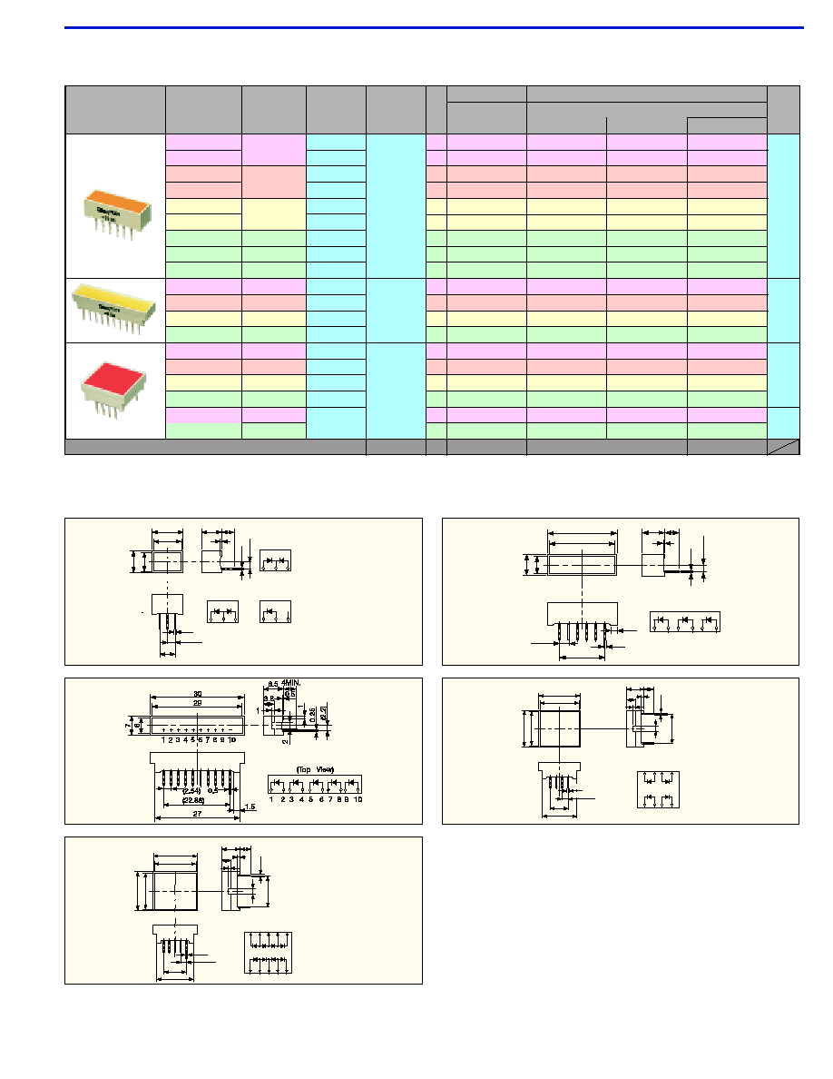
SUPER BRIGHT LED LIGHT BAR MODULE
+
1
17
16
15
(12.7)
14
2
+
7
1
0
.
25
4MIN.
(Top View)
+
+
15
2
3.5
1
(2.54)
0.5
+
+
+
+
1
3
2
4
6 5
7
8
3
4
5
6
7
8
(7.62)
fig.5
fig.6
+
17
16
15
14
+
7
1
0.
25
(12.7)
5.5MIN.
+
+
15
2
3.5
1
(2.54)
0.5
1 2
4 5
7
8
G
R G
G
G
R
R
R
+
3
+
+
+
+
+
9
10
6
7
8
9
10
6
1 2
4
5
3
(10.16)
(Top View)
fig.7
MU04-2101
MU04-2105
MU04-3101
MU04-3105
MU04-4101
MU04-4105
MU04-5101
MU04-5102
MU04-5105
MU07-2101
MU07-4101
MU07-5101
MU08-2201
MU08-3201
MU08-4201
MU08-5201
MU08-9301
Units
MU07-3101
4
20
6
x
19
(7
x
20)
20
20
20
20
20
20
20
20
20
20
20
20
20
20
20
20
20
20
mA
32
32
16
16
32
32
16
20
16
40
20
40
20
40
20
40
20
12
12
15
15
8
8
15
15
8
10
8
20
10
20
10
20
10
20
10
8
8
mcd
180
180
190
190
225
225
190
225
190
300
320
375
320
240
250
300
250
240
250
mW
3
3
3
3
3
3
3
3
3
5
5
5
5
4
4
4
4
4
4
pcs
Red
Milky White
Orange
Milky White
Yellow
Milky White
Green
Green
Milky White
Yellow
Green
Red
Orange
Yellow
Green
Green
mm
Red
Orange
Yellow
Pure Green
Green
Pure Green
Red
Orange
Red
Pure Green
Yellow
Pure Green
Red
Orange
Yellow
Pure Green
Red
Orange
6
x
29
(7
x
30)
14
x
16
(15
x
17)
5
6
7
Shape
Part No.
Emitted
Color
Resin
Color
Light
Emitting
Surface
(Outer Size)
No.
of
Chips
Absolute Max. Rating
Power Dissipation
Pd
Electro-Optical Characteristics
Luminous Intensity Iv
MIN.
TYP.
I
F
fig.
Ta=25∞C
* Lead-free soldering compatible product
*
*
*