 | –≠–ª–µ–∫—Ç—Ä–æ–Ω–Ω—ã–π –∫–æ–º–ø–æ–Ω–µ–Ω—Ç: 27C64-150 | –°–∫–∞—á–∞—Ç—å:  PDF PDF  ZIP ZIP |
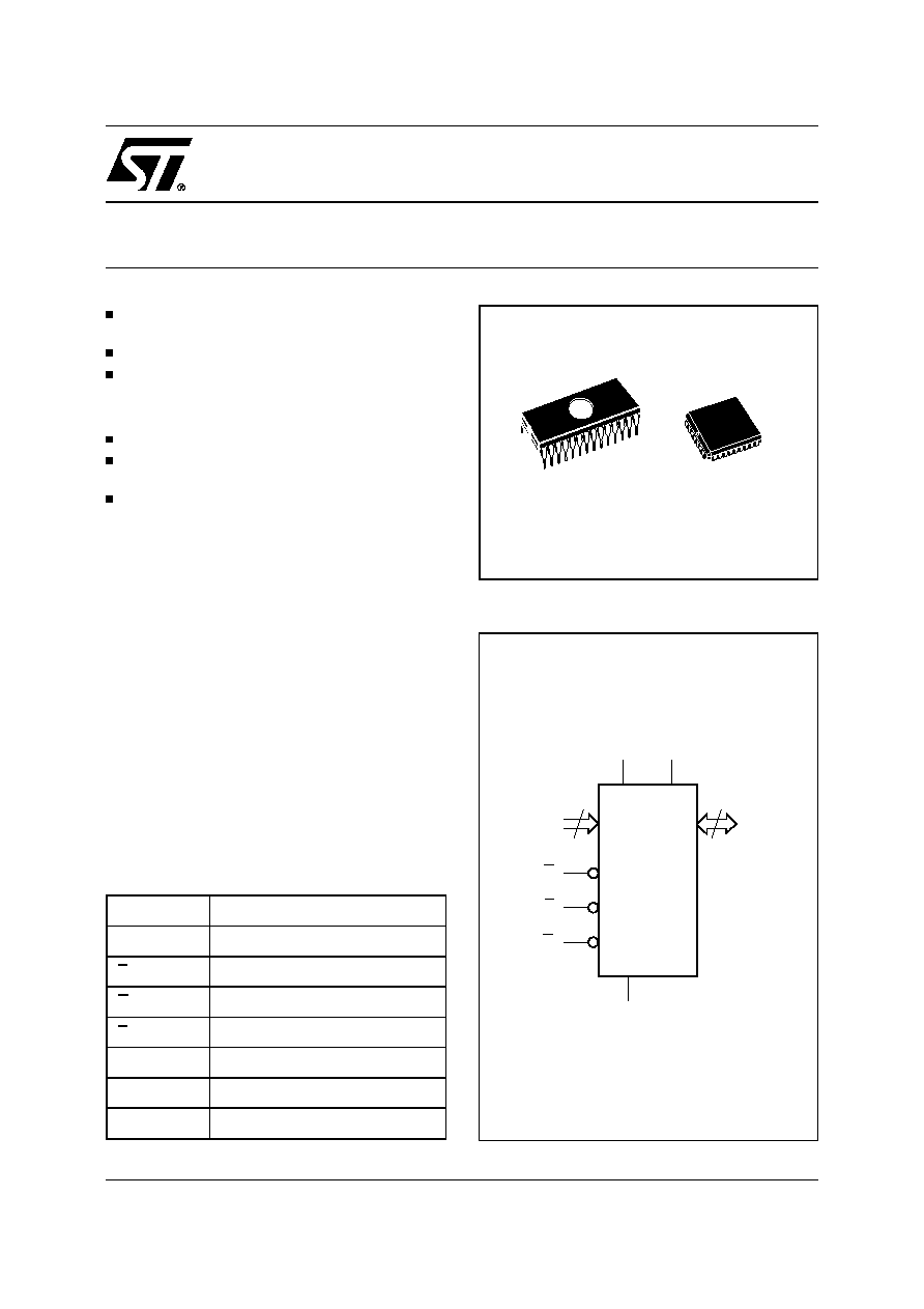
M27C64A
64 Kbit (8Kb x 8) UV EPROM and OTP EPROM
March 1998
1/12
5V
±
10% SUPPLY VOLTAGE in READ
OPERATION
FAST ACCESS TIME: 150ns
LOW POWER "CMOS" CONSUMPTION:
≠ Active Current 30mA
≠ Standby Current 100
µ
A
PROGRAMMING VOLTAGE: 12.5V
±
0.25V
HIGH SPEED PROGRAMMING
(less than 1 minute)
ELECTRONIC SIGNATURE
≠ Manufacturer Code: 9Bh
≠ Device Code: 08h
DESCRIPTION
The M27C64A is a 64Kbit EPROM offered in the
two ranges UV (ultra violet erase) and OTP (one
time programmable). It is ideally suited for micro-
processor systems requiring large programs and is
organized as 8,192 by 8 bits.
The FDIP28W (window ceramic frit-seal package)
has transparent lid which allows the user to expose
the chip to ultraviolet light to erase the bit pattern.
A new pattern can then be written to the device by
following the programming procedure.
For applications where the content is programmed
only on time and erasure is not required, the
M27C64A is offered in PLCC32 package.
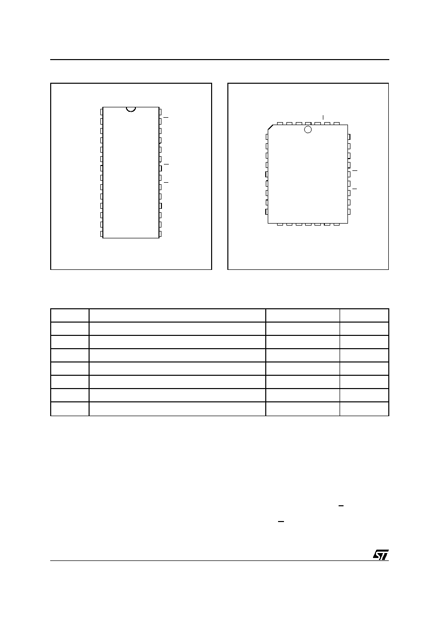
AI00834B
13
A0-A12
P
Q0-Q7
VPP
VCC
M27C64A
G
E
VSS
8
Figure 1. Logic Diagram
A0-A12
Address Inputs
Q0-Q7
Data Outputs
E
Chip Enable
G
Output Enable
P
Program
V
PP
Program Supply
V
CC
Supply Voltage
V
SS
Ground
Table 1. Signal Names
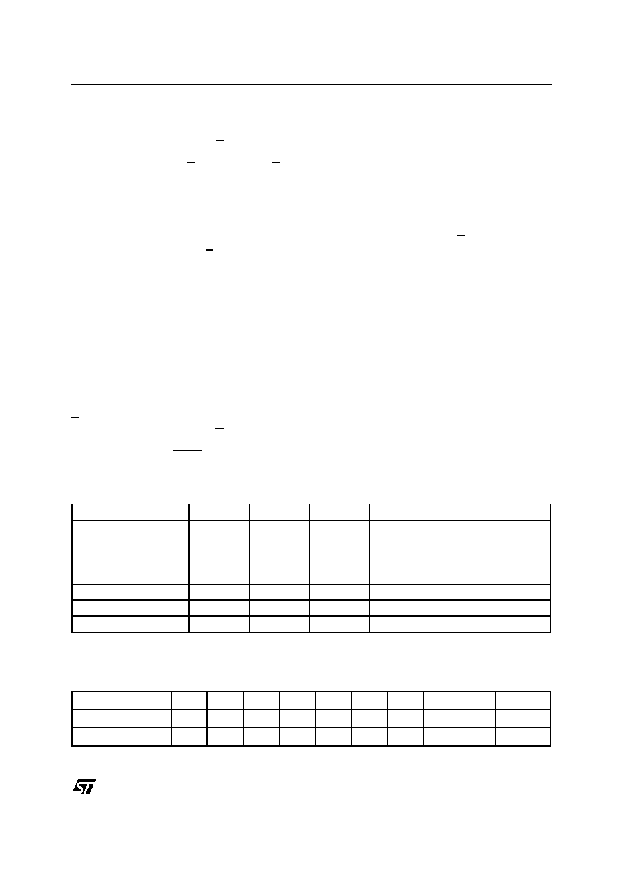
PLCC32 (C)
1
28
FDIP28W (F)
Q2
VSS
A3
A0
Q0
Q1
A2
A1
G
Q5
A10
E
Q3
A11
Q7
Q6
Q4
NC
P
A12
A4
VPP
VCC
A7
AI00835
M27C64A
8
1
2
3
4
5
6
7
9
10
11
12
13
14
20
19
18
17
16
15
A6
A5
A9
A8
28
27
26
25
24
23
22
21
Figure 2A. DIP Pin Connections
Warning: NC = Not Connected
AI00836
NC
A8
A10
Q4
17
A0
NC
Q0
Q1
Q2
DU
Q3
A6
A3
A2
A1
A5
A4
9
P
A9
1
V
PP
A11
Q6
A7
Q7
32
DU
V
CC
M27C64A
A12
NC
Q5
G
E
25
V
SS
Figure 2B. LCC Pin Connections
Warning: NC = Not Connected, DU = Don't Use
Symbol
Parameter
Value
Unit
T
A
Ambient Operating Temperature
(3)
≠40 to 125
∞
C
T
BIAS
Temperature Under Bias
≠50 to 125
∞
C
T
STG
Storage Temperature
≠65 to 150
∞
C
V
IO
(2)
Input or Output Voltages (except A9)
≠2 to 7
V
V
CC
Supply Voltage
≠2 to 7
V
V
A9
(2)
A9 Voltage
≠2 to 13.5
V
V
PP
Program Supply Voltage
≠2 to 14
V
Notes: 1. Except for the rating "Operating Temperature Range", stresses above those listed in the Table "Absolute Maximum Ratings"
may cause permanent damage to the device. These are stress ratings only and operation of the device at these or any other
conditions above those indicated in the Operating sections of this specification is not implied. Exposure to Absolute Maximum
Rating conditions for extended periods may affect device reliability. Refer also to the STMicroelectronics SURE Program and other
relevant quality documents.
2. Minimum DC voltage on Input or Output is ≠0.5V with possible undershoot to ≠2.0V for a period less than 20ns. Maximum DC
voltage on Output is V
CC
+0.5V with possible overshoot to V
CC
+2V for a period less than 20ns.
3. Depends on range.
Table 2. Absolute Maximum Ratings
(1)
DEVICE OPERATION
The modes of operation of the M27C64A are listed
in the Operating Modes table. A single power sup-
ply is required in the read mode. All inputs are TTL
levels except for V
PP
and 12V on A9 for Electronic
Signature.
Read Mode
The M27C64A has two control functions, both of
which must be logically active in order to obtain
data at the outputs. Chip Enable (E) is the power
control and should be used for device selection.
Output Enable (G) is the output control and should
2/12
M27C64A
be used to gate data to the output pins, inde-
pendent of device selection. Assuming that the
addresses are stable, the address access time
(t
AVQV
) is equal to the delay from E to output (t
ELQV
).
Data is available at the output after a delay of t
GLQV
from the falling edge of G, assuming that E has
been low and the addresses have been stable for
at least t
AVQV
-t
GLQV
.
Standby Mode
The M27C64A has a standby mode which reduces
the active current from 30mA to 100
µ
A. The
M27C64A is placed in the standby mode by apply-
ing a CMOS high signal to the E input. When in the
standby mode, the outputs are in a high impedance
state, independent of the G input.
Two Line Output Control
Because EPROMs are usually used in larger mem-
ory arrays, this product features a 2 line control
function which accommodates the use of multiple
memory connection. The two line control function
allows:
a. the lowest possible memory power dissipation,
b. complete assurance that output bus contention
will not occur.
For the most efficient use of these two control lines,
E should be decoded and used as the primary
device selecting function, while G should be made
a common connection to all devices in the array
and connected to the READ line from the system
control bus. This ensures that all deselected mem-
ory devices are in their low power standby mode
and that the output pins are only active when data
is required from a particular memory device.
System Considerations
The power switching characteristics of Advanced
CMOS EPROMs require careful decoupling of the
devices. The supply current, I
CC
, has three seg-
ments that are of interest to the system designer:
the standby current level, the active current level,
and transient current peaks that are produced by
the falling and rising edges of E. The magnitude of
the transient current peaks is dependent on the
capacitive and inductive loading of the device at the
output.
The associated transient voltage peaks can be
suppressed by complying with the two line output
control and by properly selected decoupling ca-
pacitors. It is recommended that a 0.1
µ
F ceramic
capacitor be used on every device between V
CC
and V
SS
. This should be a high frequency capacitor
of low inherent inductance and should be placed
as close to the device as possible. In addition, a
4.7
µ
F bulk electrolytic capacitor should be used
between V
CC
and V
SS
for every eight devices. The
bulk capacitor should be located near the power
supply connection point. The purpose of the bulk
capacitor is to overcome the voltage drop caused
by the inductive effects of PCB traces.
Mode
E
G
P
A9
V
PP
Q0 - Q7
Read
V
IL
V
IL
V
IH
X
V
CC
Data Out
Output Disable
V
IL
V
IH
V
IH
X
V
CC
Hi-Z
Program
V
IL
V
IH
V
IL
Pulse
X
V
PP
Data In
Verify
V
IL
V
IL
V
IH
X
V
PP
Data Out
Program Inhibit
V
IH
X
X
X
V
PP
Hi-Z
Standby
V
IH
X
X
X
V
CC
Hi-Z
Electronic Signature
V
IL
V
IL
V
IH
V
ID
V
CC
Codes
Note: X = V
IH
or V
IL
, V
ID
= 12V
±
0.5V
Table 3. Operating Modes
Identifier
A0
Q7
Q6
Q5
Q4
Q3
Q2
Q1
Q0
Hex Data
Manufacturer's Code
V
IL
1
0
0
1
1
0
1
1
9Bh
Device Code
V
IH
0
0
0
0
1
0
0
0
08h
Table 4. Electronic Signature
3/12
M27C64A

Programming
When delivered (and after each erasure for UV
EPROM), all bits of the M27C64A are in the "1"
state. Data is introduced by selectively program-
ming "0"s into the desired bit locations. Although
only "0"s will be programmed, both "1"s and "0"s
can be present in the data word. The only way to
change a "0" to a "1" is by die exposition to ultra-
violet light (UV EPROM). The M27C64A is in the
programming mode when V
pp
input is at 12.5V, E
is at V
IL
and P is pulsed to V
IL
. The data to be
programmed is applied to 8 bits in parallel to the
data output pins. The levels required for the ad-
dress and data inputs are TTL. V
CC
is specified to
be 6V
±
0.25V.
High Speed Programming
The high speed programming algorithm, described
in the flowchart, rapidly programs the M27C64A
using an efficient and reliable method, particularly
suited to the production programming environ-
ment. An individual device will take around 1 minute
to program.
Program Inhibit
Programming of multiple M27C64A in parallel with
different data is also easily accomplished. Except
for E, all like inputs including G of the parallel
M27C64A may be common. A TTL low level pulse
applied to a M27C64A P input, with E low and V
PP
at 12.5V, will program that M27C64A. A high level
E input inhibits the other M27C64A from being
programmed.
Program Verify
A verify (read) should be performed on the pro-
grammed bits to determine that they were correctly
programmed. The verify is accomplished with E
and G at V
IL
, P at V
IH
, V
PP
at 12.5V and V
CC
at 6V.
Electronic Signature
The Electronic Signature (ES) mode allows the
reading out of a binary code from an EPROM that
will identify its manufacturer and type. This mode
is intended for use by programming equipment to
automatically match the device to be programmed
with its corresponding programming algorithm. The
ES mode is functional in the 25
∞
C
±
5
∞
C ambient
temperature range that is required when program-
ming the M27C64A. To activate the ES mode, the
programming equipment must force 11.5V to 12.5V
on address line A9 of the M27C64A, with
V
PP
=V
CC
=5V. Two identifier bytes may then be
sequenced from the device outputs by toggling
address line A0 from V
IL
to V
IH
. All other address
lines must be held at V
IL
during Electronic Signa-
ture mode.
Byte 0 (A0=V
IL
) represents the manufacturer code
and byte 1 (A0=V
IH
) the device identifier code. For
the STMicroelectronics M27C64A, these two iden-
tifier bytes are given in Table 4 and can be read-out
on outputs Q0 to Q7.
4/12
M27C64A
AI00826
2.4V
0.4V
2.0V
0.8V
Figure 3. AC Testing Input Output Waveforms
Input Rise and Fall Times
20ns
Input Pulse Voltages
0.4V to 2.4V
Input and Output Timing Ref.
Voltages
0.8V to 2.0V
AC MEASUREMENT CONDITIONS
AI00828
1.3V
OUT
CL = 100pF
CL includes JIG capacitance
3.3k
1N914
DEVICE
UNDER
TEST
Figure 4. AC Testing Load Circuit
Note that Output Hi-Z is defined as the point where data
is no longer driven.
Symbol
Parameter
Test Condition
Min
Max
Unit
C
IN
Input Capacitance
V
IN
= 0V
6
pF
C
OUT
Output Capacitance
V
OUT
= 0V
12
pF
Note: 1. Sampled only, not 100% tested.
Table 5. Capacitance
(1)
(T
A
= 25
∞
C, f = 1 MHz )
AI00778B
tAXQX
tEHQZ
A0-A12
E
G
Q0-Q7
tAVQV
tGHQZ
tGLQV
tELQV
VALID
Hi-Z
VALID
Figure 5. Read Mode AC Waveforms
5/12
M27C64A