RF & MICROWAVE TRANSISTORS
S-BAND RADAR APPLICATIONS
.400 x .500 2LFL (S038)
hermetically sealed
.
REFRACTORY/GOLD METALLIZATION
.
EMITTER SITE BALLASTED
.
LOW THERMAL RESISTANCE
.
INPUT/OUTPUT MATCHING
.
OVERLAY GEOMETRY
.
METAL/CERAMIC HERMETIC PACKAGE
.
P
OUT
=
125 W MIN. WITH 7.0 dB GAIN
DESCRIPTION
The AM2729-125 device is a high power silicon
bipolar NPN transistor specifically designed for
medium pulse S-Band radar output and driver
applications.
This device is characterized at 50
µ
sec pulse
width and 10% duty cycle, but is capable of op-
eration over a range of pulse widths, duty cycles
and temperatures. Low RF thermal resistance,
refractory/gold metallization and computerized
automatic wire bonding techniques ensure high
reliability and product consistency (including
phase characteristics).
The AM2729-125 is supplied in the BIGPAC
TM
Hermetic Metal/Ceramic package with internal In-
put/Output impedance matching circuitry, and is
intended for military and other high reliability ap-
plications.
PIN CONNECTION
BRANDING
2729-125
ORDER CODE
AM2729-125
ABSOLUTE MAXIMUM RATINGS (T
case
=
25
∞
C)
Symbol
Parameter
Value
Uni t
P
DISS
Power Dissipation*
(T
C
75
∞
C)
500
W
I
C
Device Current*
16
A
V
CC
Collector-Supply Voltage*
45
V
T
J
Junction Temperature (Pulsed RF Operation)
250
∞
C
T
STG
Storage Temperature
-
65 to +200
∞
C
R
TH(j-c)
Junction-Case Thermal Resistance*
0.35
∞
C/W
*Applies only to rated RF amplifier operation
AM2729-125
1. Collector
3. Emitter
2. Base
4. Base
THERMAL DATA

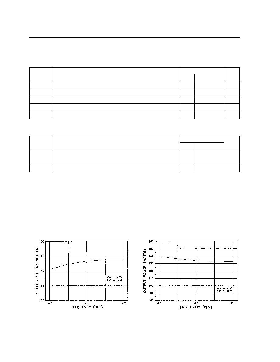
TYPICAL EFFICIENCY @ 2.7 GHz
TYPICAL EFFICIENCY @ 2.8 GHz
TYPICAL EFFICIENCY @ 2.9 GHz
TYPICAL PERFORMANCE @ 2.7 GHz
TYPICAL PERFORMANCE @ 2.8 GHz
TYPICAL PERFORMANCE @ 2.9 GHz
TYPICAL PERFORMANCE (cont'd)
AM2729-125
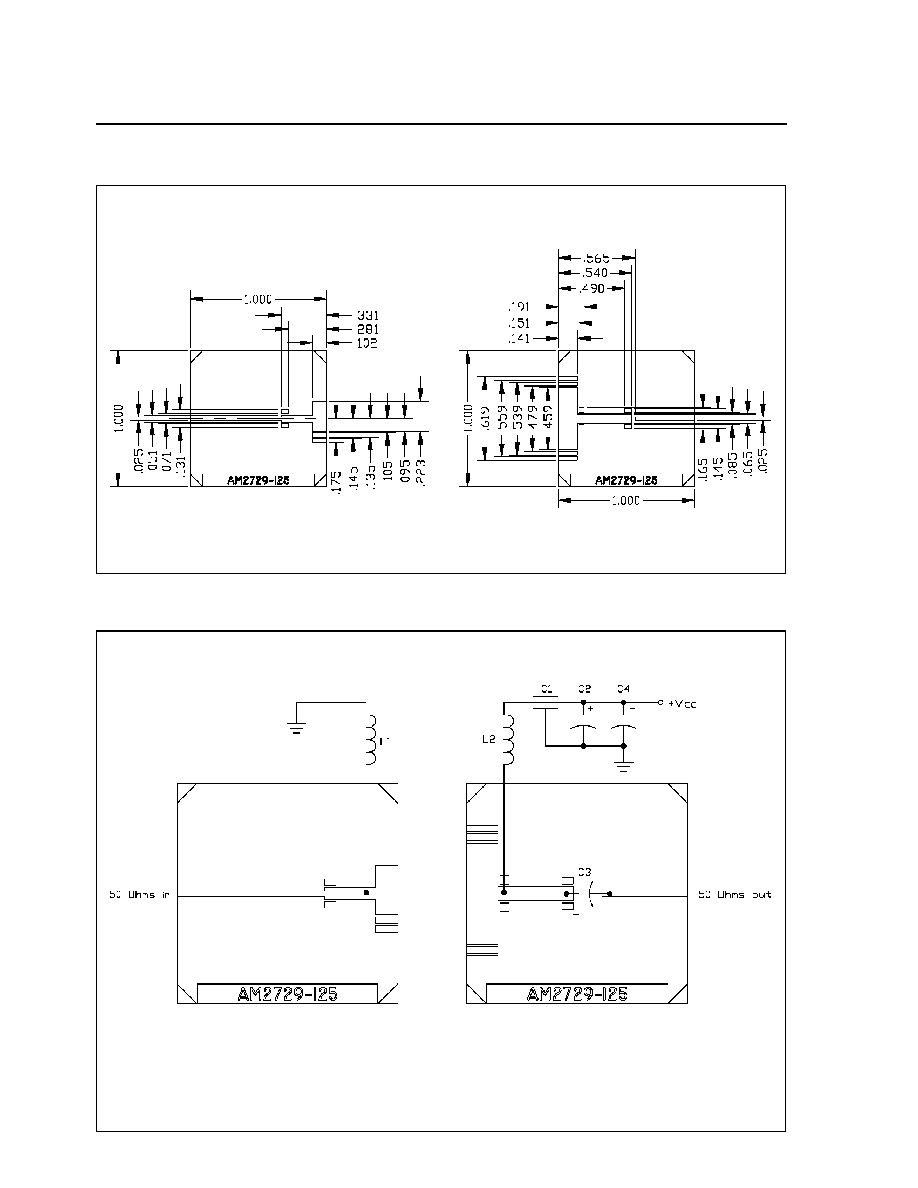
TEST CIRCUIT
All dimensions are in inches
C1
:
1000pf RF Feedthrough
C2
:
0.1
µ
F, 100V Ceramic Capacitor
C3
:
33pf Microwave Chip Capacitor
C4
:
100
µ
F, 63V Electrolytic Capacitor
L1, L2 :
#26 Wire, 2 Turns, 0.08" I.D.
Board Material: Alumina, Er = 9.6, H = 25mil
AM2729-125