 | –≠–ª–µ–∫—Ç—Ä–æ–Ω–Ω—ã–π –∫–æ–º–ø–æ–Ω–µ–Ω—Ç: AN1113 | –°–∫–∞—á–∞—Ç—å:  PDF PDF  ZIP ZIP |

January 1999
INTRODUCTION
Brushless DC motors (BLDC) are becoming widely used in the field of control motors. These kind of syn-
chronous motors are used as servo drives in applications such as computer peripherals equipment, ro-
botics, and as adjustable-speed drives in load-proportional capacity-modulated heat pumps, large fans ,
compressors and so on.
Brushless DC motors are referred to by many aliases as brushless permanent magnet, permanent ma-
gnet AC motors, permanent magnet synchronous motors, etc. The confusion arises because a brush-
less motor does not directly operate off a dc voltage source. It is generally driven (supplied) from an in-
verter which converts a constant voltage to a 3-phase voltage with a frequency corresponding
instantaneously to the rotor speed.
One of the advantages of BLDC motor is the sparks absence. The brushes of a DC motor have several
problems as regards to brushes' life and dust residues, maximum speed and electrical noise. BLDC mo-
tors are potentially cleaner, faster, more efficient, less noisy and more reliable. However, BLDC motors
require a more complex electronic control.
This application note will show how this complexity can be reduced by using ST52x301 Fuzzy controller.
AN OUTLINE OF BRUSHLESS MOTORS
The Brushless motor has the physical appearance of a 3-phase permanent magnet synchronous machi-
ne.
The brushes and commutator have been eliminated and the windings are connected to the control elec-
tronics. Electronics replaces the function of the commutator and energizes the proper winding. The ener-
gized stator winding leads the rotor magnet and switches just as the rotor aligns with the stator.
In synchronous motor drives, the stator is supplied with a set of balanced three-phase currents, whose
frequency is
f.
If
p is the number of the poles in the motor, then:
f
=
p
4
s
(1)
where
s
(rad/s) is the flux synchronous speed or, that is the same, the rotor speed. This equation links
the rotor speed to the phases switching frequency of the electronic drive.
The above currents produce a constant amplitude flux
s
in the air gap, which rotates at the synchro-
nous speed
s
. Since the flux amplitude is proportional to the current amplitude, it is enough to manage
winding current level to control the rotor torque.
From Brushless theory [3-4] it is possible to demonstrate that
T
em
=
K
t
f
I
ph
sin
()
(2)
where k
t
is a constant,
f
is the field-flux,
is called torque angle.
represents the angle between the
phase linked flux
fph1
and the relative stator current I
ph1
.
AN1113
APPLICATION NOTE
Brushless Motor Fuzzy Control by using ST52x301
Authors: G. Grasso, M. Di Guardo
1/18

Now, if the electronic controller is able to supply phase
Ph1 in order to maintain
=90∞ the equation abo-
ve (2) can be simplified as
T
em
=
K
T
I
s
(3)
where K
T
is called motor torque constant and I
s
is the amplitude of the stator phase currents. From the
previous considerations it is clear the reason why a BLDC motor needs always position sensors to know
exactly rotor position. Fig. 1 shows a transversal section of a typical three phase brushless motor.
Figure 1 . Three-phase brushless motor
Figure 2. Motor Data Sheet
H1
H2
H3
Linked Voltage for Counterclockwise direction
In the diagram, three position sensors (Hall sensors) are placed around the rotor in order to detect the
shaft position. Fig. 2 reports motor data sheet supplied by the motor builder.
Æ
AN1113 - APPLICATION NOTE
2/18

By observing the motor data sheet, these concepts become clear. In fact, it is possible to see the rela-
tion between shaft position, hall sensors response and voltage profile to be supplied.
This way to supply the stator phases is very complex because it is necessary to produce a sine wave
with a proper period and delay with respect to the sensors information. As we will show later on, a sim-
pler method is possible.
INVERTER DRIVER TOPOLOGY
The stator of a brushless DC motor is generally supplied by an inverter which converts a DC voltage to a
3-phase AC voltage whose frequency is related to the speed of the rotor. Speed control is achieved by a
Pulse Width Modulation (PWM) of the phases voltage accomplished by periodically switching the phase
voltage to zero. The widely used driver to perform this switching is the six-step inverter where each pha-
se is driven by means of a couple of transistors. Fig.3 shows the basic operating principle of this drive.
The name "six-steps" arises from the finite time-steps in which the whole period can be shared. During
each time step, current direction does not change whereas current amplitude can increase or decrease
in the coil.
To better explain this operating principle, let us consider the action of one leg (phase) of the inverter,
such as for example T1 and T4.
Transistor T1 is turned on at
= - 90∞and turned off at
=90∞ while T4 is turned on at
=90∞. When T1 is
Figure 3. Inverter driver operating principle
turned off, the current it was carrying is immediately diverted to the diode in parallel with T4. This diode
re-circulates the instantaneous current of the winding until it decreases to zero.
Once the phase current reverses direction is carried by T4. In term of voltage it is easy to draw the pha-
ses voltages by conceiving the transistors as switches. Due to the triangular connection of the phases,
each phase voltage depends by the status of two legs of the bridge. Figure 4 shows one real phase star
voltage and one phase current. Six voltage steps are evident in the look like sine wave.
The same happens in the other legs of the bridge in different times. This topology drives the windings for
the whole period, avoiding the phase to be "floating" (Six-Steps Continuous Mode Inverter).
FUZZY CONTROLLER
Ph 3
U
T2
T3
T5
T6
T1
T2
T3
0
/2
3
/2
=
t
T1
T4
Ph 1
V
Ph 2
W
Æ
Brushless Motor Fuzzy Control by using ST52x301
3/18

The aim of the control is to maintain the desired Speed regardless of the applied load to the shaft. When
a resistance torque is applied to the shaft, a reduction of the speed takes place. This implies an incre-
ment in the wave period of the Hall sensors signals and then a decrement of the sine frequency in the
phases, to follow sensors information.
In this case, the only way to lead the rotor at the previous speed is to increase the winding current in or-
der to balance the load torque. Fuzzy Controller, in fig. 6, performs this task. ST52x301 reads the speed
Figure 4. Phase voltage and current
Figure 5. Control topology
Speed_Ref
Error
FUZZY
CONTROLLER
PWM
MOTOR
DRIVER
Speed
Æ
AN1113 - APPLICATION NOTE
4/18
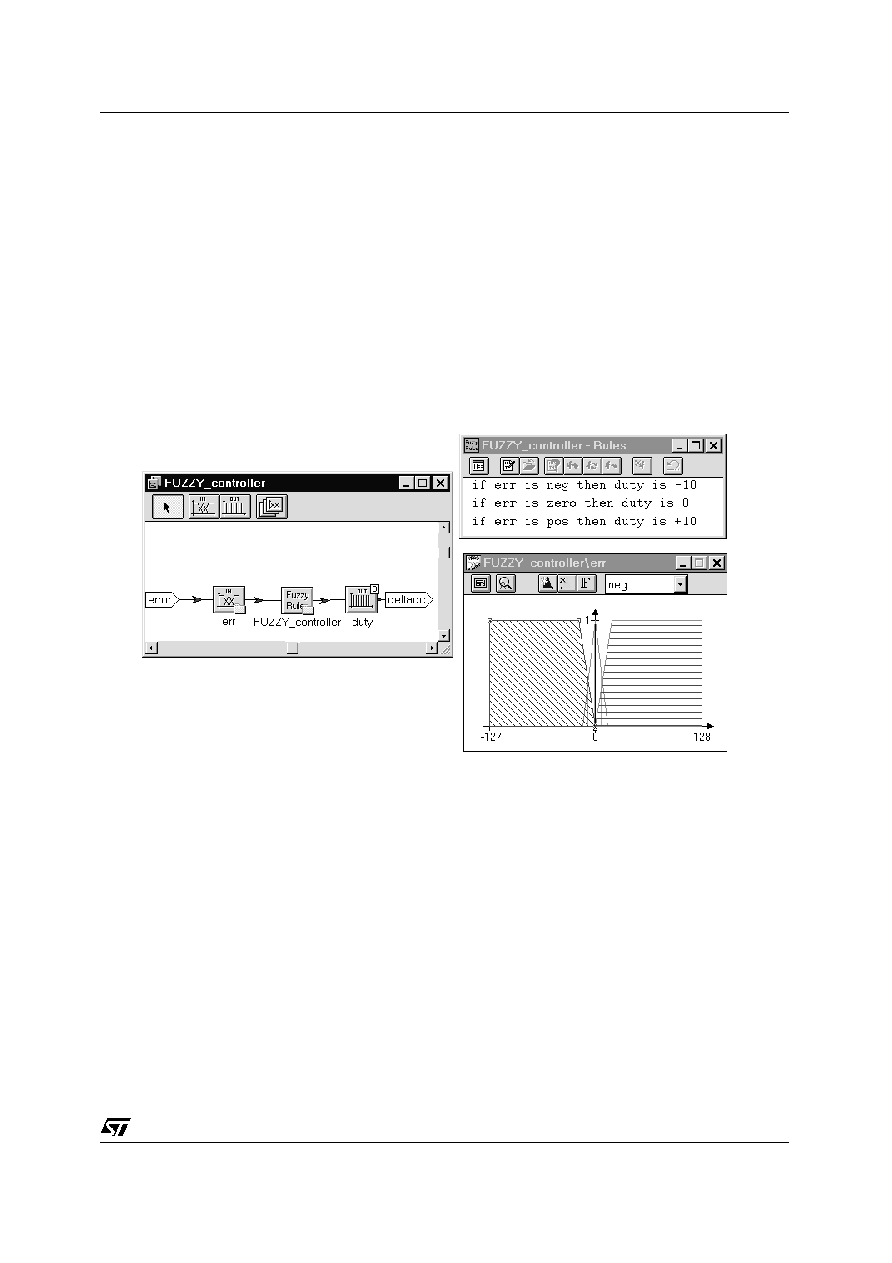
"Ref" value from AD Channel0 and the instantaneous Hall signal period by means of a digital port. A
software task performs the "error" calculation
error
=
VREF
-
speed.
The variable "
Error" also forms the Fuzzy Input for the "Fuzzy Controller" block. A Fuzzy algorithm uses
three rules to compute the fuzzy-out, achieving an incremental variable to drive the inverter in real-time
mode.
This incremental method allows to manage the speed in a closed loop real-time control, since software
task time is very short.
The first rule is fully activated when "error" value is "neg", i.e. when Vref <<speed. This implies that the
actual speed of the shaft is higher than "Ref". Then the action to carry out is to reduce the phase current
Figure 6. Fuzzy algorithm
I. To achieve this, it is necessary to decrease the PWM duty-cycle. The displayed value "-10" is a good
compromise between system stability and step response of the system. This value was assigned after
some trials by using only human reasoning. Instead, If the duty step is higher, for example "-20", the sy-
stem will sooner reach the "Speed_Ref" but the overshoot in a step response could lead to instability.
The above explanation is similar for the other rules.
The implemented 3-rules fuzzy algorithm is the simplest way to control the speed. A more accurate con-
trol could be done by using first derivative of the speed to improve the action strenght by means of other
rules.
HARDWARE DESCRIPTION
Æ
Brushless Motor Fuzzy Control by using ST52x301
5/18