 | –≠–ª–µ–∫—Ç—Ä–æ–Ω–Ω—ã–π –∫–æ–º–ø–æ–Ω–µ–Ω—Ç: AN1354 | –°–∫–∞—á–∞—Ç—å:  PDF PDF  ZIP ZIP |

1/10
Æ
April 2002
L.Gonthier
Up to now, refrigerator compressors have been controlled by electromechanical switches (thermostat or
even electronically controlled relays). This choice was driven by the high inrush current that can appear
when the rotor is stalled. Furthermore, electromechanical relays are advantageous because they are less
sensitive to line voltage disturbances. Today, new semiconductor devices feature over-voltage protection
and high inrush current capability, allowing them to be used in cold appliances.
Electronic thermostats can so be implemented, allowing the appliance efficiency to be improved by more
than 20 W, for 150 W compressors, thanks to better temperature control and the removal of the PTC.
Hence, at a similar cost as Electromechanical thermostats, this technical breakthrough could allow refrigerators
or freezers to fulfill Class A consumption requirements, bringing the following advantages:
s
Better reliability:
- Higher switching robustness of static switches towards mechanic solutions
- Higher ACS and ACST overvoltage robustness towards Triacs, which allows Metal-Oxyde varistor
removal
s
Temperature regulation law flexibility (automatic defrost, Hysteresis threshold adaptation)
s
Reduction of the temperature ripple (better food preservation, appliance elements downsizing)
s
Possibility to add indication features for the end-user (inside temperature, open door)
s
Spark-free operation and EMI reduction (switches can be turned on at Zero Voltage and are turned off at
Zero Current)
s
Overcurrent protection of the motor winding.
This paper outlines the different topologies that can be used for electronic motor control, and lists the
electrical constraints that result from these different circuits. A comparison is also made between the
different performances of electromechanical or electronic thermostats.
All numerical examples are based on the specifications for a 1/5 Horse power compressor, which can be
used in 350 L freezers
1.INTRODUCTION
AN1354
APPLICATION NOTE
SINGLE-PHASE INDUCTION MOTOR DRIVE FOR
REFRIGERATOR COMPRESSOR APPLICATION
A.S.D
TM
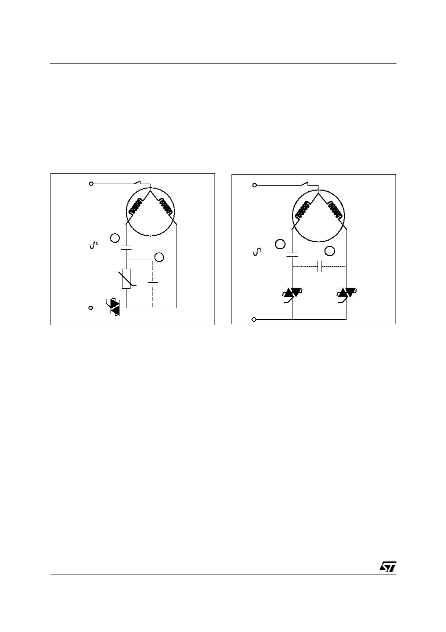
Single-phase induction motors, used for compressor controls, embed an auxiliary winding. This winding
permits a higher torque at start-up to be applied. Two different ways can be implemented to control this
auxiliary winding. The different topologies are given in Figures 1 and 2.
The most popular method is to add a Positive Temperature Coefficient (PTC) resistor in series with this coil
and the thermostat (cf. Figure 1). Then, each time the thermostat is closed, the current flows through the
Start winding and begins to heat the PTC. After a few hundreds of milliseconds, the PTC value rapidly in-
creases from a few Ohms to several tens of kOhm. This results in reducing the Start winding current to a
few tens of mAmps. This winding can then be considered as open.
A second solution is to use a second triac to control the auxiliary winding and then replace the PTC duty
(cf. Figure 2). Then, at START Triac OFF state, no power is consumed contrary to the PTC, this results in
an improvement in the appliance efficiency (cf. 4.2.1 section).
2.1 One or Two Triac approach
2. SINGLE-PHASE INDUCTION MOTOR DRIVE TOPOLOGIES
APPLICATION NOTE
2/10
A start capacitor is sometimes connected in series with this winding in place 1 (cf. Figures 1 and 2). It is im-
portant to note, even for the same motor, that this capacitor can be placed or removed, without disturbing
the motor operation.
When C is placed in Position 2 (split-phase capacitor), it always sinks a current, even when the PTC is hot
or when the START triac is OFF. This allows power factor improvement and power consumption reduction.
In fact, the C capacitor will be added if the refrigerator or freezer does not reach the required efficiency level
without it.
In the following study, we assume that C is always placed at Position 2, if present.
C
V
AC
1
PTC
2
T(∞C) Klixon
Run ACST
Fig. 1: One-triac topology
C
V
AC
1
PTC
2
T(∞C) Klixon
Run ACST
Start ACST
Fig. 2: Two-triac topology
2.2 Semiconductor rating
The start capacitor and the auxiliary winding form a resonant R-L-C circuit. The capacitor voltage can thus
be higher that the mains one. In practice the ratio between V
C
and Vac equals 1.1 to 1.5.
The worst case appears at the run triac turn-off, for both topologies. Indeed, V
C
is added to the mains volt-
age up to the capacitor complete discharge. This results in high voltages across the run triac (cf. Figure 3).
Even for a 220-240 V application, 700 V semiconductors must then be chosen.
2.2.1 Start-capacitor voltage

APPLICATION NOTE
3/10
Fig. 3: Voltage across run triac after turn-off (612V max)
Refrigerator or freezer compressors mostly feature input power in the range of 100-300 W. The steady
state current is then in the range of 0.5 to 3 A RMS for a 220-240 V mains voltage.
The highest current appears at start-up and can reach up to 4 times the steady state current. Thermal cal-
culations can demonstrate that, as these events last a short time, 6 A devices can be used without any heat
sink. For example, Figure 4 gives the junction temperature increase of an ACST6-7ST without any heat
sink, due to the inrush current which is measured through the start winding of a 1/5 Horse power compres-
sor. It shows that Tj only reaches 72 ∞C, when coming from a 60 ∞C ambient temperature, and remains be-
low the maximum allowed temperature (125 ∞C).
2.2.2 Current rating
Fig. 4: Inrush current in START winding (1/5 Horse power compressor)
APPLICATION NOTE
4/10
When dealing with the current rating for AC semiconductor switches, the rate of decrease of the current
must also be checked. This constraint will depend on the chosen topology.
The worst case of turn-off stress appears with a compressor without any start capacitor. In this case, the
rise in voltage will not be slowed by the motor capacitor. The higher stress occurs for the "START" winding
(where the impedance is lower than the "RUN" winding one) and when the rotor is stalled. These two condi-
tions yield a higher current and therefore, a higher rate of decrease for the ACST current.
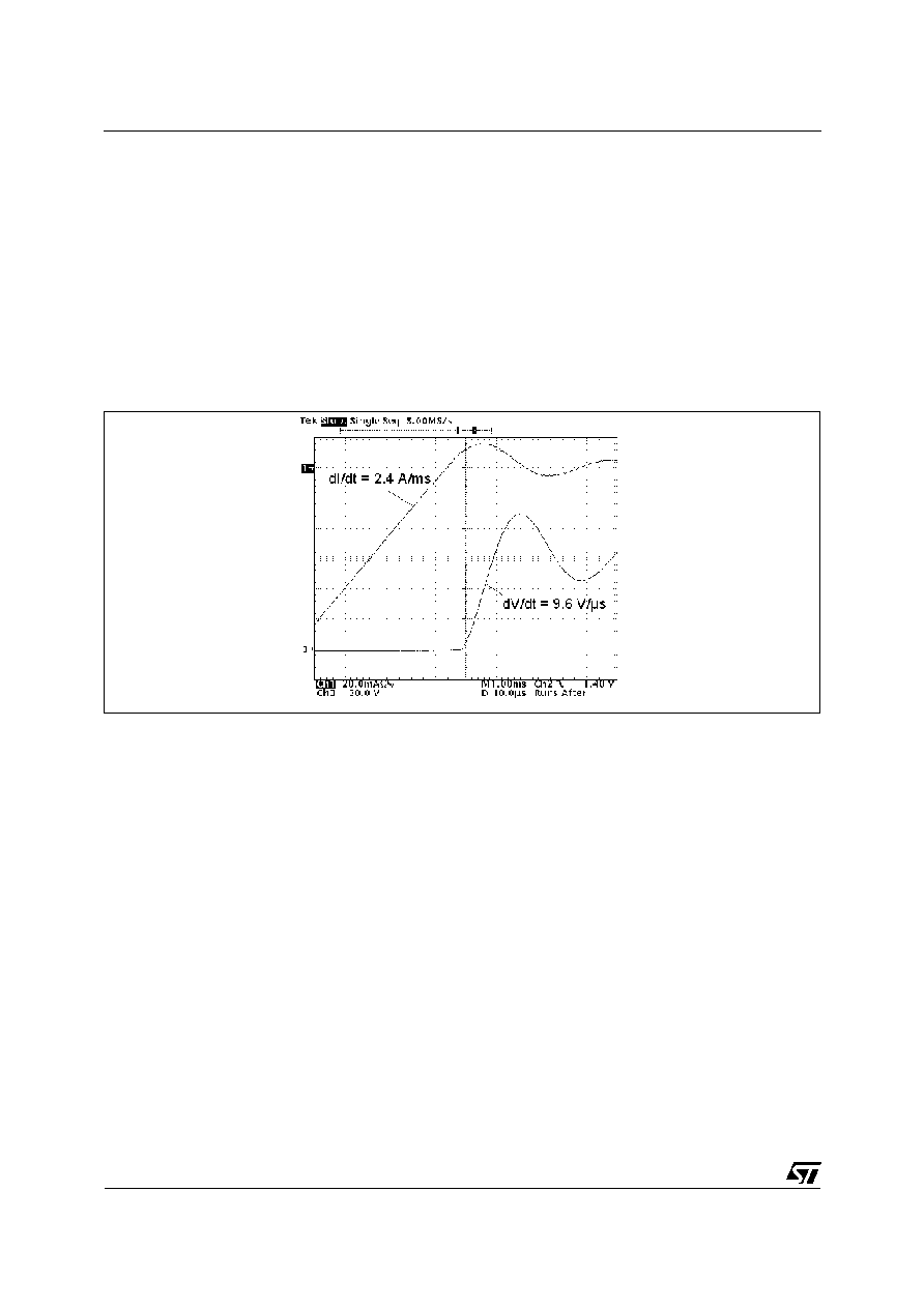
Then, for a stalled 1/5 Horse power compressor, supplied with a 264 V RMS voltage, the dI/dtc and dV/dtc
equals respectively 2.4 A/ms and 9.6 V/µs through the START ACST (cf. Figure 5, measured with
THERM01EVAL board). This is far below the maximum withstanding for ACST6 devices, which is 3.5 A/ms
with a 15 V/µs rate.
Fig. 5: Turn-off constraint for the worst case scenario
With the two-triac topology, a spurious discharge of the start-capacitor can occur when the start-triac is ac-
cidentally turned on. To reduce the dI/dt stress through the silicon switch, a small protective inductor can be
added in series with this triac.
In order to optimize the solution cost, this inductor can be achieved in Printed Circuit Board (PCB). For ex-
ample, a double-sided inductor with 12 turns of 0.51 mm width track (cf. Figure 6), made on a 35 µm-FR4
PCB, yield to a 5 µH ≠ 1.6 Ohm resistor.
An inductor as described in Figure 6, allows the dI/dt rate to be limited, in case of a spurious firing of the
START ACST when the RUN ACST is already on, below 60 A/µs (start capacitor is charged up to 510 V).
The semiconductor device operation is then well secured.
2.3 Protective inductor

APPLICATION NOTE
5/10
2.8cm
Fig. 6: 5µH PCB inductor
3. STALLED ROTOR MANAGEMENT
In the case of a stalled rotor operation, the over current protection is commonly ensured by a thermal
cut-off. This component, also called "klixon", is mandatory to prevent the compressor from over-heating.
Klixons are well adapted for motor protection, but not for semiconductors. Indeed, the turn-off time is in the
range of 15 s. The silicon switch will withstand a high current that will only decrease thanks to the motor
winding heating. In practice, the RMS current can fall from 9 A RMS to around 4.5 A RMS, for a 1/5 horse
power compressor.
The maximum junction temperature reached by the ACST6-7ST can then equal 160 ∞C as shown by the
simulation results in Figure 7.
As this temperature exceeds the maximum allowed steady state temperature of the triac (125 ∞C), reliabil-
ity tests have been performed to check the robustness of the silicon switches after such stress. ACST6 de-
vices can then withstand such currents up to more than 10 thousand times. This easily covers the number
of stalled rotor operations that can happen during the life cycle of a refrigerator or freezer.
3.1 Protection by thermal cut-off
Fig. 7: Triac junction temperature during stalled rotor operation