 | –≠–ª–µ–∫—Ç—Ä–æ–Ω–Ω—ã–π –∫–æ–º–ø–æ–Ω–µ–Ω—Ç: AVS08CBI | –°–∫–∞—á–∞—Ç—å:  PDF PDF  ZIP ZIP |
AUTOMATIC VOLTAGE SWITCH (SMPS < 200W)
CONTROLLER
50/60Hz FULL COMPATIBILITY
INTEGRATED VOLTAGE REGULATOR
TRIGGERING PULSE TRAIN OF THE TRIAC
PARASITIC FILTER
LOW POWER CONSUMPTION
TRIAC
HIGH EFFICIENCY AND SAFETY SWITCHING
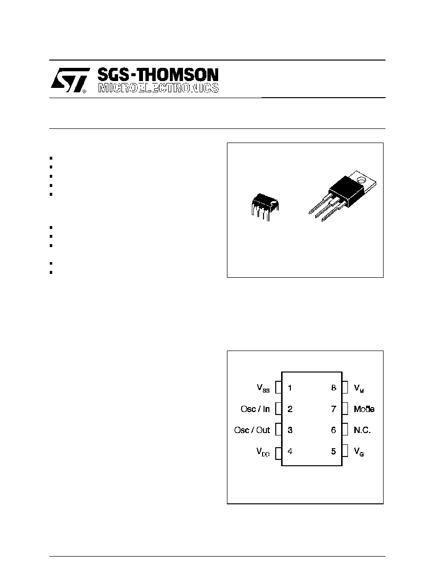
UNINSULATED PACKAGE : AVS08CB
INSULATED
PACKAGE
2500V(
RMS
)
:
AVS08CBI
V
DRM
=
±
500 V
I
T(RMS)
: 5A
DESCRIPTION
The AVS08 kit is an automatic mains selector
(110/220V AC) to be used in SMPS < 200 W. It is
composed of 2 devices :
∑
The Controller is optimized for low consumption
and high security triggering of the triac. When
connected to V
SS
, the mode input activates an
additional option. If the main power drops from
220V to 110V, the triac control remains locked to
the 220V mode and avoids any high voltage spike
when the voltage is restored to 220V.
When connected to V
DD
, the mode input desacti-
vates this option.
∑
The TRIAC is specially designed for this applica-
tion. An optimization between sensitivity and dy-
namic parameters of the triac gate highly reduces
the losses of supply resistor and allows excellent
immunity against disturbances.
P
DIP8
(Plastic)
B
TO220AB
(Plastic)
A1
A2
G
AVS08
March1995
PIN CONNECTION
1/7
ABSOLUTE MAXIMUM RATINGS
CONTROLLER AVS1BCP08
(1) Gate supply : IG = 100mA ≠ di/dt = 1A/
µ
s
(2) Tj = 125
∞
C
Symbol
Parameter
Value
Unit
Min.
Max.
VSS
Supply voltage
- 12
0.5
V
VI / VO
I / O voltage
V
SS
- 0.5
0.5
V
II / IO
I / O current
- 40
+ 40
mA
Tstg
Storage Temperature
- 60
+ 150
∞
C
Toper
Operating Temperature code
" C "
0
+ 70
∞
C
TRIAC AVS08CB / AVS08CBI T
j
= +25
∞
C (unless otherwise specified)
Symbol
Parameter
Value
Unit
VDRM
Repetitive peak off-state voltage (2)
±
500
V
IT(RMS)
RMS on-state current
(360
∞
conduction angle)
AVS08CB
T
C
= 100
∞
C
5
A
AVS08CBI
T
C
= 95
∞
C
ITSM
Non repetitive surge peak on-state current
( T
j
initial = 25
∞
C )
t = 8.3ms
t = 10ms
70
65
A
I2t
I
2
t value
t = 10ms
21
A2s
dI/dt
Critical rate of rise of on-state current (1)
Repetitive
F = 50Hz
20
A/
µ
s
Non
Repetitive
100
Tstg
Tj
Storage Temperature
Junction Temperature Range
- 40 + 125
- 10 + 110
∞
C
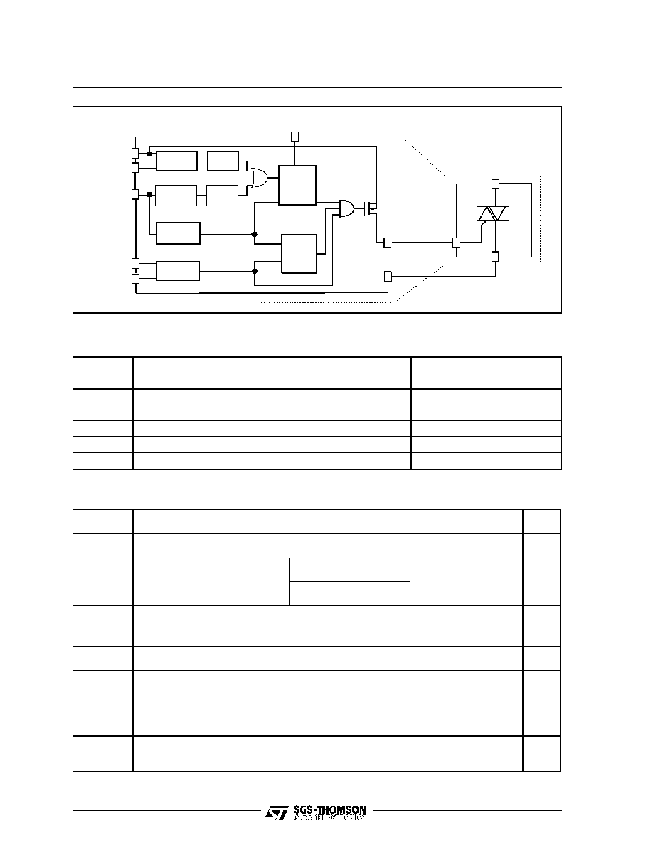
Q
Q
Reset
CP
S
CP
OSC/IN
OSC/OUT
MODE
Parasitic
Filter
Peak Voltage
Dectector
A1
A2
Triggering
Time
Controller
Supply
1
4
8
2
3
Oscillator
Zero Crossing
Detector
5
3
4
2
1
V
V
G
G
DD
7
DD
V
V
V
M
SS
Mains
mode
Controller
MR
AVS1BCP08
AVS08CB
or
AVS08CBI
BLOCK DIAGRAM
AVS08
2/7
* For either polarity of electrode A2 voltage with reference to electrode A1.
DC GENERAL ELECTRICAL CHARACTERISTICS
TRIAC AVS08CB / AVS08CBI
Symbol
Parameter
Value
Unit
Min.
Max.
VTM *
ITM = 7A
tp = 10ms
T
j
= 25
∞
C
1.65
V
IDRM *
VDRM rated
Gate open
T
j
= 25
∞
C
10
µ
A
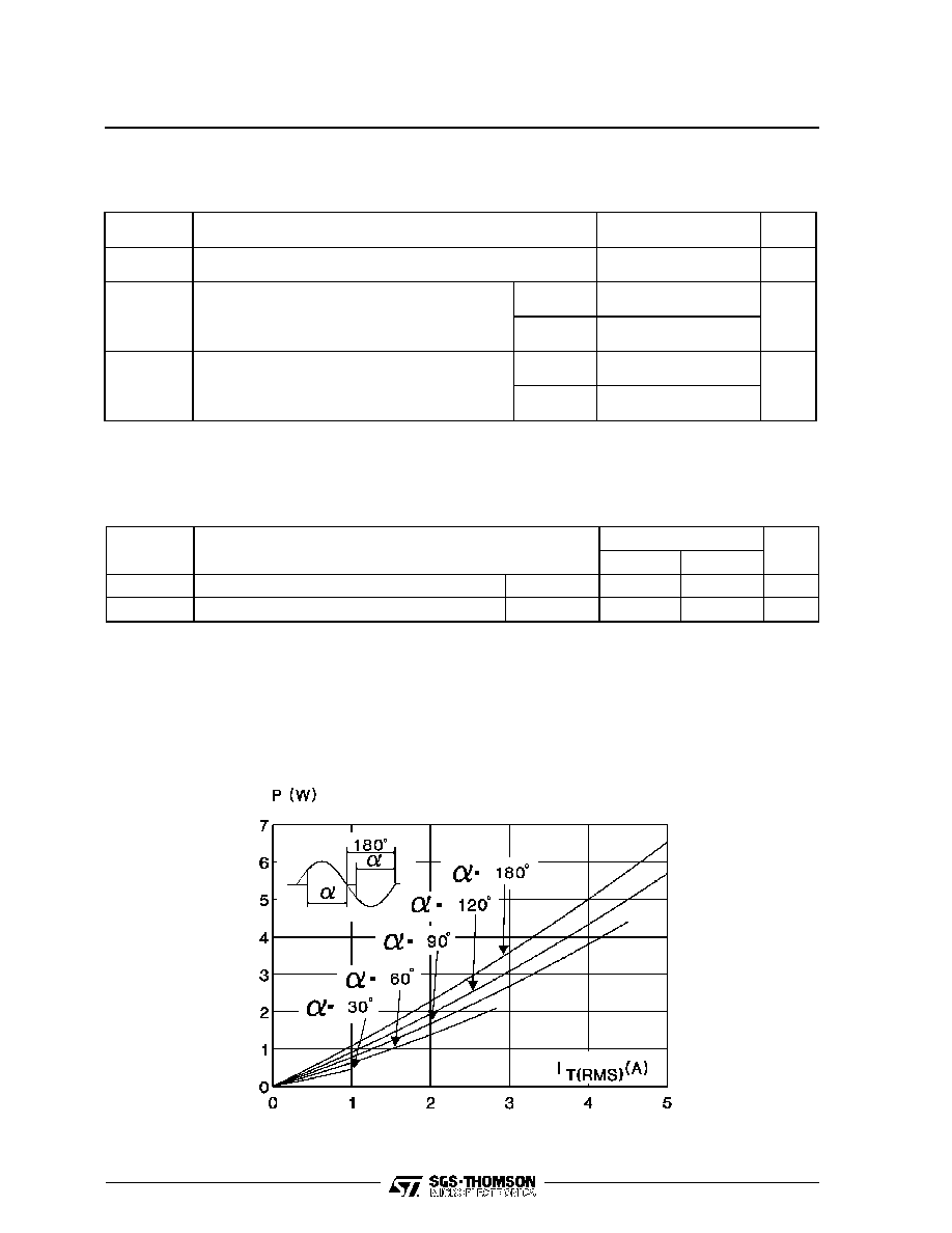
Fig. 1 :Maximum RMS power dissipation versus RMS on-state current
(F = 60Hz).
(Curves are cut off by (dI/dt)c limitation)
THERMAL RESISTANCES
TRIAC AVS08CB / AVS08CBI
Symbol
Parameter
Value
Unit
Rth (j-a)
Junction-to-ambient
60
∞
C/W
Rth (j-c) DC
Junction-to-case for DC
AVS08CB
5.4
∞
C/W
AVS08CBI
6.3
Rth (j-c) AC
Junction-to-case for 360
∞
conduction angle
( F = 50Hz)
AVS08CB
4.0
∞
C/W
AVS08CBI
4.7
AVS08
3/7

Symbol
Parameter
Value
Unit
Min
Typ
Max
VSS (pin 1) (Vreg)
Shunt regulator
- 10
- 9
- 8
V
ISS (pin 1) (Vreg)
(@ VSS = 9V)
Supply current
0.4
25
mA
ISS (pin 1)
(@ triac gate non
connected)
Quiescent current
1
mA
F (pin 3)
(@ R = 91k
)
(C = 100pF)
Oscillator frequency
42
44
46
KHz
VM (pin 8) Vth (3)
Peak voltage of detection
high-threshold
4.08
4.25
4.42
V
VM (pin 8) Vh (3)
Peak voltage of detection hysteresis
0.370
0.4
0.420
V
(1) VM (pin 8) Vth (3)
Zero-crossing detection
high-threshold
95
110
125
mV
VM (pin 8) Vh (3)
Zero-crossing detection hysteresis
27
50
80
mV
(2)
Vrazht (4)
Power-on-reset activation threshold
Vreg x 0.89
V
(2)
Vrazlt (4)
Power-down-reset activation
threshold
3
6.95
V
Mode (pin 7)
VIL
(4)
VIH
(4)
0.7 Vreg
0.3 Vreg
V
VG (pin 5)
VOL (IVG = 25mA)
Leakage current (VG = VDD)
1
+ 50
V
µ
A
DC GENERAL ELECTRICAL CHARACTERISTICS (continued)
CONTROLLER AVS1BCP08 T
oper
= 25
∞
C (unless otherwise specified)
NOTES :
(1) : This value gives a typical noise immunity on the zero-crossing detectionof 110mV x 1018/18 = 6.20V on the main supply
(2) : See following diagram
(3) : Voltage referred to VSS
(4) : Voltage referred to VDD
0V
0V
-2.7V
-2.7V
Vrazht
Vrazlt
Vreg = V
- V
SS
DD
Normal oper at ion
Power-on
reset
Undeter mined
Undetermi ned
Reset
power-off
POWER-ON AND POWER-OFF RESET BEHAVIOUR
AVS08
4/7
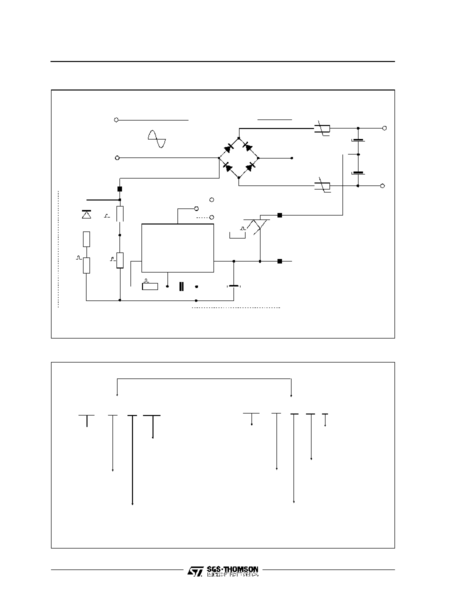
option
7
5
4
NTC
NTC
110 V
or
220V
G
1 N
4007
R1
1M
1 %
8
3
2
1
A
1
A
2
V
V
DD
SS
V
DD
V
G
V
M
91k 1 %
100pF 5 %
V
SS
2
x
9.1K
1W
R2
18K
1 %
390
AVS08CB
or AVS08CBI
AVS08
AVS1BCP08
33
µ
F
16V
TYPICAL APPLICATION
ORDERING INFORMATION
AVS08
CONTROLLER
AVS
1B
C P08
AVS 08
C
B
I
TRIAC
OPERATING TEMPERATURE :
C = 0/70
∞
C
OPERATING TEMPERATURE :
C = 0/70
∞
C
IDENTIFICATION
PACKAGE :
DIP 8
AUTOMATIC
VOLTAGE
SWITCH
PACKAGE B:
UNINSULATED TO220
INSULATED Suffix
IDENTIFICATION
AUTOMATIC
VOLTAGE
SWIT CH
AVS08
5/7