
AVS20
AVS200
AUTOMATIC VOLTAGE SWITCH (SMPS < 300W)
July 1992
1
2
3
4
V
Mode
NC
V
8
7
6
5
Osc/Out
Osc/ In
V
V
SS
DD
M
G
AVS20-01.EPS
DIP8
PIN CONNECTIONS
P
DIP8
(Plastic Package)
ORDER CODE : AVS2ACP08
CONTROLLER
.
50/60Hz FULL COMPATIBILITY
.
INTEGRATED VOLTAGE REGULATOR
.
TRIAC TRIGGERING BY PULSE TRAIN
.
HIGH IMMUNITY TO AC DISTURBANCES
(SPIKES, MISSING CYCLE)
.
HIGH RELIABILITY ON LINE VOLTAGE DE-
TECTION (PARASITIC FILTER ON SIGNAL IN-
PUT)
.
FAST DIGITAL START-UP TIME
(< 2 LINE CYCLES)
.
LOW POWER CONSUMPTION
TRIAC
.
HIGH EFFICIENCY AND SAFETY SWITCHING
.
UNINSULATED PACKAGE :
AVS10CB/AVS100CB
.
INSULATED PACKAGE (2500V
RMS
) :
AVS10CBI
.
V
DRM
=
�
600V (AVS10CB),
�
800V (AVS100CB)
.
I
T(RMS)
: 8A
DESCRIPTION
The AVS20 (AVS200) kit is an automatic mains
selector (120/230V AC) to be used in SMPS with
input power < 300 W. It is composed of 2 devices :
�
The Controller is optimized for low consumption
and high security triggering of the triac. When
connected to V
SS
, the mode input activates an
additional option "the latched option". If the
main power drops from 230V to 120V, the triac
control remains locked to the 230V mode and
avoids any high voltage spike when the voltage
is restored to 230V.
When connected to V
DD
, the mode input desac-
tivates this option "this is the follower option".
�
The TRIAC is specially designed for this applica-
tion. An optimization between sensitivity and
dynamic parameters of the triac gate highly re-
duces the losses of supply resistor and allows
excellent immunity against line disturbances.
B
TO220AB
(Plastic Package)
ORDER CODES : AVS10CB-AVS10CBI-AVS100CB
1/8

RESET
PARASITIC
FILTER
LATCHED
MODE
CONTROL
MAINS
MODE
CONTROLLER
TRIAC
TRIGGERING
WINDOW
CLOCK
10
PARASITIC
FILTER
PARASITIC
FILTER
0.05
0.25
4.25
8
2
3
SUPPLY
RST
4
1
7
5
PEAK LINE VOLTAGE DETECTOR
CROSSING DETECTOR
R
CK
R
R
CK
CK
2
1
3
V
G
G
A1
A2
4
V
M
V
DD
V
SS
V
DD
MODE
OSC/IN
OSC/OUT
AVS2ACP08
AVS100CB
AVS10CB
AVS10CBI
or
AVS20-02.EPS
BLOCK DIAGRAM
ABSOLUTE MAXIMUM RATINGS
CONTROLLER AVS2ACP08
Symbol
Parameter
Min.
Max.
Unit
V
SS
Supply voltage
- 12
0.5
V
V
I
/ V
O
I / O voltage
V
SS
- 0.5
0.5
V
I
I
/ I
O
I / O current
- 40
+ 40
mA
T
stg
Storage Temperature
- 60
+ 150
�
C
T
op er
Operating Temperature code
" C "
0
+ 70
�
C
AVS20-01.TBL
TRIAC AVS10CB / AVS10CBI / AVS100CB T
j
= +25
�
C (unless otherwise specified)
Symbol
Parameter
Value
Unit
V
DRM
Repetitive peak off-state voltage (2)
AVS10
AVS100
�
600
�
800
V
V
I
T(RMS)
RMS on-state current (360
�
conduction angle)
T
C
= 80
�
C, AVS10CB/AVS100CB
T
C
= 70
�
C, AVS10CBI
8
8
A
A
I
TSM
Non repetitive surge peak on-state current ( T
j
initial = 25
�
C )
t = 8.3ms
t = 10ms
85
80
A
A
I
2
t
I
2
t value (t = 10ms)
32
A
2
s
di/dt
Critical rate of rise of on-state current (1)
Repetitive f = 50Hz
Non Repetitive
20
100
A/
�
s
A/
�
s
dv/dt (3)
Linear slope up to 400V (Gate open) (T
j
= 70
�
C)
AVS10
AVS100
75
150
V/
�
s
V/
�
s
T
stg
Storage Temperature
-40, +150
o
C
T
j
Operating Junction Temperature
0, +110
o
C
(1) Gate supply : I
G
= 100mA � di/dt = 1A
/
�
s
(2) T
j
= 110
�
C
(3) For either polarity of electrode A
2
voltage with reference to electrode A
1
AVS20-02.TBL
AVS20 - AVS200
2/8

THERMAL RESISTANCES
TRIAC AVS10CB / AVS10CBI / AVS100CB
Symbol
Parameter
Value
Unit
R
th (j-a)
Junction-to-ambient
60
o
C/W
R
th (j-c)
DC
Junction-to-case for DC
AVS10CB / AVS100CB
AVS10CBI
3.5
4.4
o
C/W
o
C/W
R
th (j-c)
AC
Junction-to-case for 360
�
conduction angle ( f = 50Hz)
AVS10CB / AVS100CB
AVS10CBI
2.6
3.3
o
C/W
o
C/W
AVS20-03.TBL
DC GENERAL ELECTRICAL CHARACTERISTICS
TRIAC AVS10CB / AVS10CBI / AVS100CB
Symbol
Parameter
Min.
Max.
Unit
V
GD
V
D
= V
DRM
R
L
= 3.3k
Pulse duration> 20
�
s (T
j
= 110
�
C)
0.2
V
V
TM
(1)
I
TM
= 11A (t
p
= 10ms, T
j
= 25
�
C)
1.75
V
I
DRM
(1)
V
DRM
rated
Gate open
T
j
= 25
�
C
AVS10/AVS100
T
j
= 110
�
C
AVS10
T
j
= 700
�
C
AVS100
10
500
500
�
A
�
A
�
A
AVS20-04.TBL
Symbol
Parameter
Min.
Typ.
Max.
Unit
MAIN CHARACTERISTICS
V
SS
(pin 1) (Vreg)
Shunt Regulator Voltage
- 10
- 9
- 8
V
I
SS
(pin 1) (Vreg)
(@ V
SS
= -9V)
Supply Current
0.4
30
mA
I
SS
(pin 1)
(@ triac gate non connected)
Quiescent Current
0.6
0.7
mA
F (pin 3)
(@ R = 91k
) (C = 100pF)
Oscillator Frequency
42
44
46
kHz
V
PWRON
(2)
Power-on-reset Threshold
0.89 Vreg
V
PWROFF
(2)
Power-off-reset Threshold
4.6
V
Mode (pin 7)
V
IL
(2)
V
IH
(2)
0.7 Vreg
0.3 Vreg
V
G
(pin 5)
V
OL
(I
VG
= 25mA)
Leakage Current (V
G
= V
DD
)
650
+ 10
mV
�
A
PEAK LINE VOLTAGE DETECTOR
V
SWON
(pin 8)
Low Threshold of Trip Point
(switching-on of triac triggering) (3)
3.89
4.05
4.22
V
V
SWOFF
(pin 8)
High Threshold of Trip Point
(switching-off of triac triggering) (3)
4.08
4.25
4.42
V
t
ON
(pin 5)
Triac Turn-on Delay Time
(V
AC
= 120V)
1
2
Line
cycles
ZERO VOLTAGE CROSSING DETECTOR
V
0CR
PH (pin8)
High Threshold on Positive AC Side (3)
250
mV
V
0CR
PL (pin8)
Low Threshold on Positive AC Side (3) (4)
200
mV
V
0CR
NH (pin8)
High Threshold on Negative AC Side (3)
100
mV
V
0CR
NL (pin8)
Low Threshold on Negative AC Side (3) (4)
60
mV
NOTES :
(1) : For either polarity of electrode A
2
voltage with reference to electrode A
1
.
(2) : Voltage referred to V
DD
.
(3) : Voltage referred to V
SS
.
(4) : These values give a typical noise immunity on the zero-crossing detection of 100mV x
1018
18
= 5.65V on the mains supply.
AVS20-05.TBL
CONTROLLER AVS2ACP08 T
oper
= 25
�
C (unless otherwise specified)
AVS20 - AVS200
3/8
AVS20-03.EPS
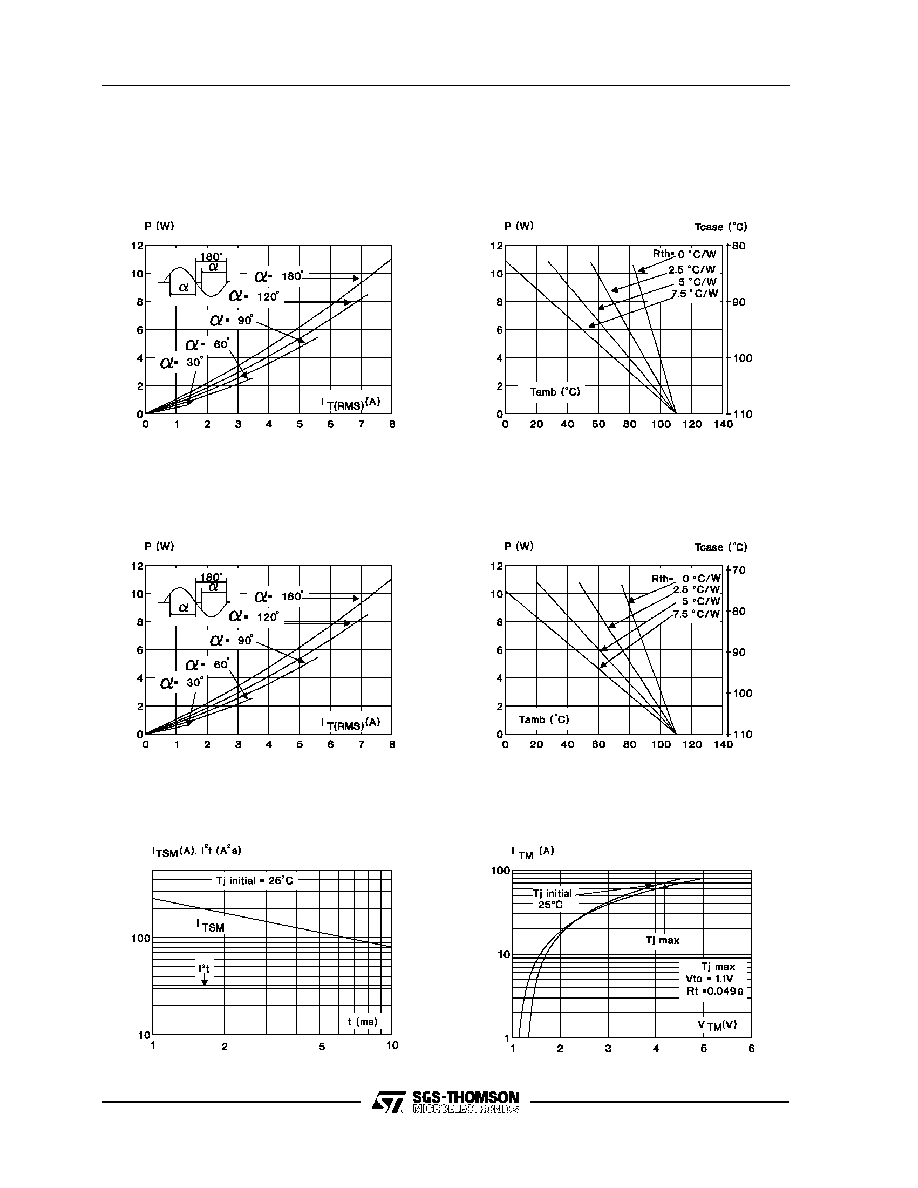
Figure 1: Maximum RMS power dissipation
versus RMS on-state current (f=60Hz)
(Curves are cut-off (di/dt)
c
limitation)
AVS20-04.EPS
Figure 2a : Correlation between maximum mean
power dissipation and maximum
allowable temperatures (T
A
and T
C
)
for different thermal resistances
heatsink + contact
(AVS10CB/AVS100CB)
AVS20-03.EPS
AVS20-05.EPS
Figure 2b : Correlation between maximum mean
power dissipation and maximum
allowable temperatures (T
A
and T
C
)
for different thermal resistances
heatsink + contact (AVS10CBI)
AVS20-07.EPS
Figure 4 : On-state characteristics
(maximum values).
AVS20-06.EPS
Figure 3 : Non-repetitive surge peak on-state
current for a sinusoidal pulse with
width : t
10ms, and corresponding
value of I
2
t.
AVS20 - AVS200
4/8
option
NTC
NTC
110 V
or
220V
G
1 N
4007
R1
1M
1 %
33
�
F
16V
A
1
A
2
V
V
DD
SS
V
DD
V
G
V
M
91k 1 %
100pF 5 %
V
SS
2
x
9.1K
1W
R2
18K
1 %
390
AVS20
AVS2ACP08
AVS10CB/CBI
or AVS100CB
7
8
5
3
2
1
4
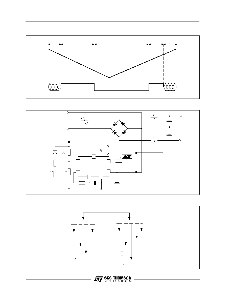
AVS20-09.EPS
TYPICAL APPLICATION DIAGRAM
Undetermine d
Power-on reset
Normal operation
Undetermined
S S
DD
Vreg = V
- V
-3V
-3V
V
PWRON
V
PWROFF
0V
0V
Power-off
Reset
AVS20-08.EPS
POWER-ON AND POWER-OFF RESET BEHAVIOUR
AVS20/AVS200
CONTROLLER
TRIAC
AVS 2A
C
P08
AVS
C
10
B
I
AUTOMATIC
VOLTAGE
SWITCH
IDENTIFICATION
PACKAGE :
DIP8
OPERATING TEMPERATURE :
C = 0/70 C
AUTOMATIC
VOLTAGE
SWITCH
INSULATED Suffix
PACKAGE B :
UNINSULATED TO220
OPERATING TEMPERATURE :
C = 0/70 C
IDENTIFICATION
V
600V
800V
10
100
:
=
V
:
=
DRM
DRM
AVS20-10.EPS
ORDERING INFORMATION
AVS20 - AVS200
5/8