FEATURES
Uko INTERFACE (DC) and MAINS (AC) inputs
to enable NPM (Normal Power Mode) and
RPM (Restricted Power Mode) CONDITIONS
INPUT FILTER TO MEET EMI requirements
PEAK INPUT OVERVOLTAGE WITHSTAND-
ING
AC INPUT PROTECTION FUSE
INPUTS TO OUTPUTS INSULATION
2 INSULATED OUTPUTS:
Vo1=5 V for NT1 logics
Vo2=40 V for "S" interface
AUXILIARY LOGIC OUTPUT TTL-COMPAT-
IBLE for LED & NPM/RPM MODE indication.
PS1 and PS2 output TTL-compatible
INTERNAL RELAY FUNCTION FOR Vo2 PO-
LARITY REVERSE
U-INTERFACE ACCORDING TO ETR080
"S" INTERFACE OUTPUT CHARAC-
TERISTICS:
- Peak output of 220 mA for 150 ms
- Typical output power 4,5 W
- Output filtering to meet ETSI requirements
- Hold up time: 20 ms with 4,5 W output power
- Continuous short circuit protection
- Peak overvoltage withstand:1KV for 10/700 us
transversal
S-INTERFACE ACCORDING TO ETS 300
012
MTBF: 300 Kh, according to MIL HDBK 217-F
Operating Temperature: -10 to +70
o
C
May 2001
Æ
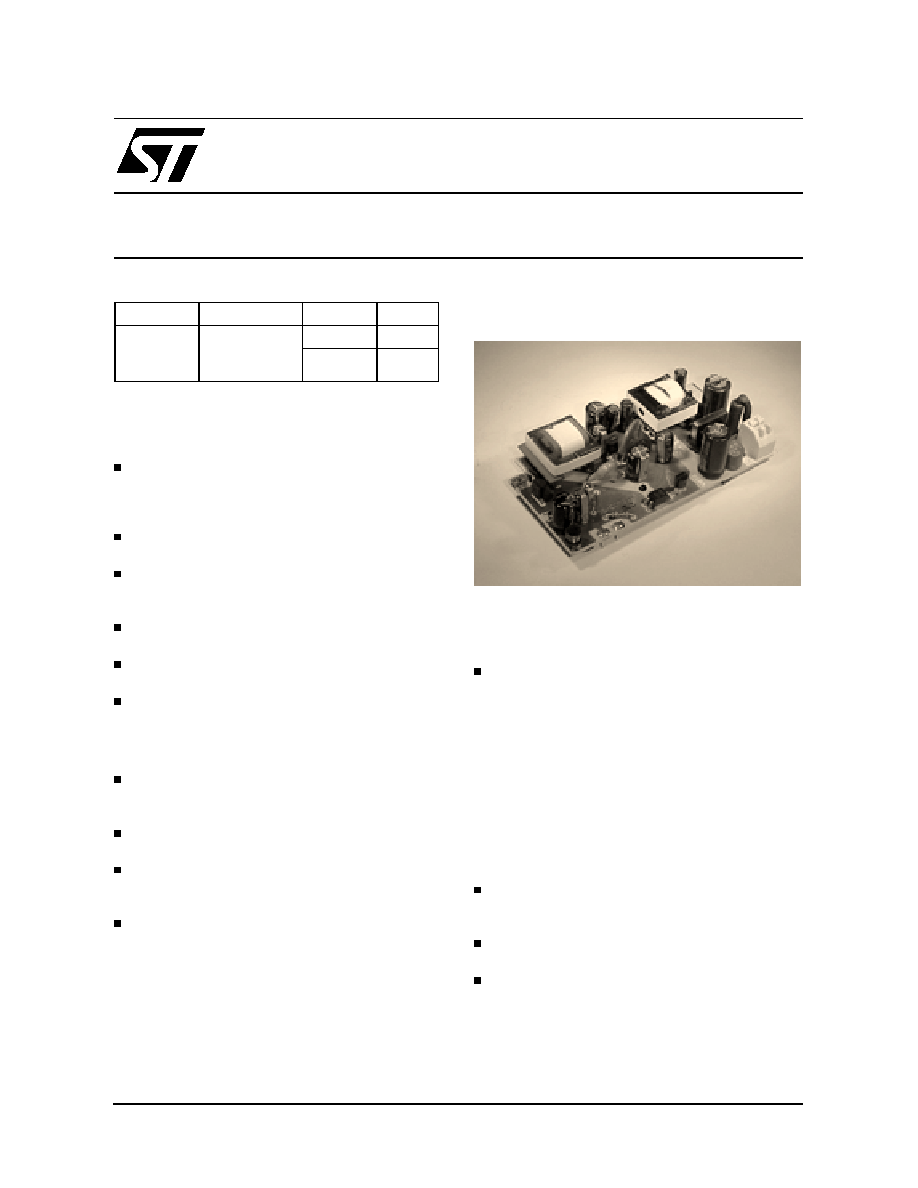
PRODUCT VIEW
ORDERING NUMBER: GS-COMBI/E1-I
COMBI/E1-I
Power Management Module for
ISDN NT1
SPECIFICATION Rev. 02
Type
Vi
Vo
Io
COMBI/E1-I
195 to 253 Vac
and
28 to 115 Vdc
out1: 5 V
80 mA
out 2: 40V
120 mA
1/6

DESCRIPTION
The NT1 Power Management Module COMBI/E1-
I is a comprehensive solution for ISDN-NT1 (Net-
work Termination Basic Access NTBA) equip-
ment, combining both AC-DC and DC-DC
functions.
The GS-COMBI/E1-I provide the NTBA with all
necessary supply voltages as well as control sig-
nals to operate in the different operating modes,
typically the Normal Power Mode (NPM) and Re-
stricted Power Mode (RPM).
Connected to the main, Input 1 (2 poles AC con-
nector) is the AC input power to the COMBI/E1-I,
source of the whole necessary power in normal
operating mode, namely in NPM. Input 2 is the
DC power source when in RPM, therefore to con-
nect to the U-INTERFACE.
The device supply 5V (out 1) for logics and 40 V
(out 2) for the S interface both in Normal Power
Mode (NPM) and in Restricted Power Mode
(RPM).
RPM mode is the emergency condition that oc-
curs if the mains (AC) input is not available. An
internal "relay function" is available to reverse the
40 V output polarity. A third auxiliary output can
be used for LEDs driving and RPM/NPM mode
acknowledge (Logic output).
The Logic output becomes high (+5V) when in
NPM condition.
PS1 and PS2 signal overload at the S-interface
(PS1 in NPM and PS2 in RPM)
The converter offers short-circuit protection on
both outputs: particularly, short-circuit on 40V out-
put doesn't affect the +5V output.
Out 1, out 2... out 5 share the same common re-
turn.
3000 VRMS insulation voltage for 60 seconds (re-
inforced insulation) is provided among input 1
and all outputs. Same reinforced insulation is also
provided between Input 1 and Input 2.
2000 VRMS / 1 min. reinforced insulation is pro-
vided between input 2 and all outputs.
When in NPM mode (AC main supply), the mod-
ule max. power consumption is <15 VA (apparent
power).
Input 2 undervoltage lockout offers high imped-
ance in order to have 10 uA max input current
when Vi2 is <18 Volts.
The design of the module has been conducted
using the following reference standards:
EN 60950, VDE0878 part 1 class B (EMC),
EN55022 class B (emission), EN50 082-1 (immu-
nity) ITU-T I.430, ETS 300 012 and ETR 080 and
ETS300 047 (ISDN BASIC ACCESS, Safety and
Protection); anyway, please note that no certifica-
tion processes have been carried out on the mod-
ule itself.
COMBI/E1-I
2/6
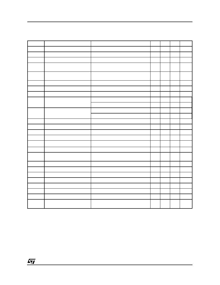
ELECTRICAL CHARACTERISTICS when in NPM (Tamb=25
o
C, unless otherwise specified.)
NPM Standard Condition: Vin1 = 195 to 253 Vrms Vin2 = 28 to 115 Vdc
Symbol
Parameter
Test Condition
Min.
Typ.
Max.
Unit
Vi1
Input Voltage 1
195
253
VRMS
Vi2
Input Voltage 2
any polarity
28
115
Vdc
fi
Vi1 Input Frequency
Vi1 = 230 VRMS
43
56
Hz
Vi1st
Start up Input 1 voltage
Output parameters as per NPM
Standard Conditions
185
VRMS
Vi2st
Start up Input 2 voltage
Output parameters as per Standards
Conditions
44
Vdc
Vo1
Output Voltage 1
Standard conditions
4.75
5
5.25
V
Vo2
Output Voltage 2
Standard conditions
36
40
42
V
Vo3
Output Voltage 3
Standard conditions, Io3=0.9 to 3mA
4.5
5
5.25
V
Vo4
Output Voltage 4
Vo2 > 34 v (normal load)
4.75
5
5.25
V
(PS 2)
Vo2 < 24v (overload)
4.75
5
5.25
V
Vo5
Output Voltage 5
Vo2> 34v (normal load)
4.75
5
5.25
V
(PS 1)
Vo2 < 24v (overload)
0.8
V
Vor1
Output Ripple voltage 1
Standard conditions BW: 0-20 MHz
20
mVrms
Vor2
Output Ripple voltage 2
Standard conditions BW: 0-20 MHz
100
mVrms
Io1
Output Current 1
Standard conditions
3
80
mA
Io2
Output Current 2
Standard conditions
0
120
mA
Ioc2
Output Overcurrent 2
t=150ms, Vo1=34 to 42 V
220
240
260
mA
Io2sc
Output 2 short circuit current
Continuous short circuit
20
40
60
mA
Vi1th
NPM => RPM mode Vi1
threshold
Output parameters as per Standard
Conditions
160
Vrms
Ttr
Transition time
transition NPM => RPM and vice versa
5
ms
Vi1pk
Input 1 Transient overvoltage
t = 8/20 us transversal
2
kV
Vi2pk
Input 2 Transient overvoltage
t= 10/700 us transversal
500
V
Vo2pk
Output 1 Transient overvoltage
t = 10/700 us transversal
1000
V
Pi1r
Input 1 Real Power
NPM standard conditions
9
W
Pi1
Input 1 Apparent Power
NPM standard conditions
15
VA
Vist
Insulation Voltage, pulse
INputs to outputs t=10/700 us (pulse)
4
kV
th
Hold-up time
Vin=195 VRMS Pout 1:0 to 340 mW
Pout 2: 4.5 W
20
ms
COMBI/E1-I
3/6
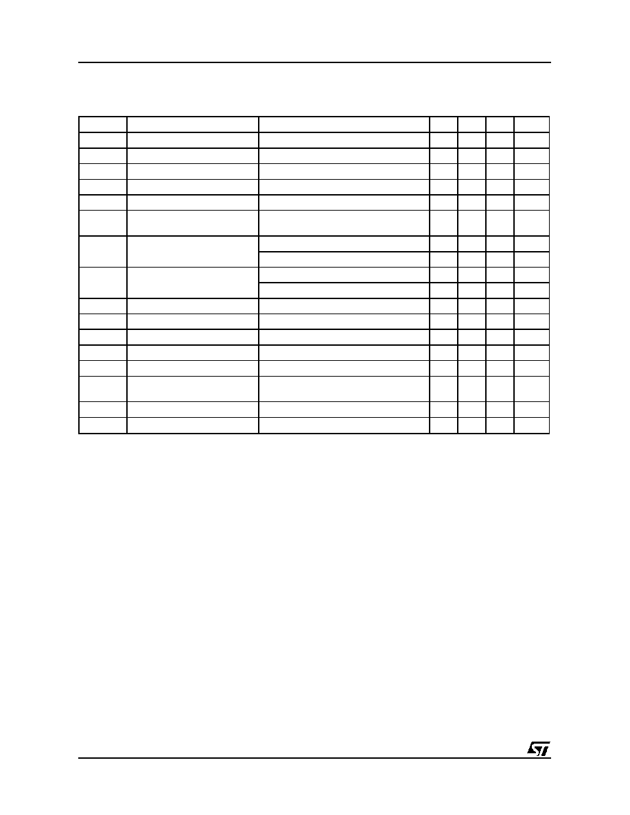
ELECTRICAL CHARACTERISTICS when in RPM (Tamb=25
o
C, unless otherwise specified.)
RPM Standard Condition: Vin1 < 100 Vrms Vin2 = 28 to 115 Vdc
Symbol
Parameter
Test Condition
Min.
Typ.
Max.
Unit
Vi1
Input Voltage 1
0
100
Vrms
Vi2
Input Voltage 2
any polarity
28
115
Vdc
Vi2st
Start Up Input 2 Voltage
44
Vdc
Vo1
Output Voltage 1
RPM Standard Conditions
4.75
5
5.25
V
Vo2
Output Voltage 2
RPM Standard Conditions
34
40
42
V
Vo3
Output Voltage 3
RPM Standard conditions, out 3 load=50
kOhm
0.8
V
Vo4
Output Voltage 4
Vo2 > 34v (normal load)
4.75
5
5.25
V
(PS 2)
Vo2 < 24v (overload)
0.8
V
Vo5
Output Voltage 5
Vo2 > 34v (normal load)
0.8
V
(PS 1)
Vo2 < 24v (overload)
0.8
V
Vor1
Output Ripple Voltage 1
RPM Standard Conditions BW:0-20 Mhz
20
mVrms
Vor2
Output Ripple Voltage 2
RPM Standard Conditions BW:0-20 Mhz
100
mVrms
Io1
Output Current 1
RPM Standard Conditions
3
80
mA
Io2
Output Current 2
RPM Standard Conditions
0
12.5
mA
Io2sc
Output 2 short circuit current
Continuous short circuit
9
13.5
mA
Vi1th
RPM=>NPM mode Vi1
threshold
185
VRMS
Ttr
Transition time
transition NPM => RPM and vice versa
5
ms
Vi1pk
Input 1 Transient overvoltage
t = 8/20 us transversal
2.0
Kv
COMBI/E1-I
4/6
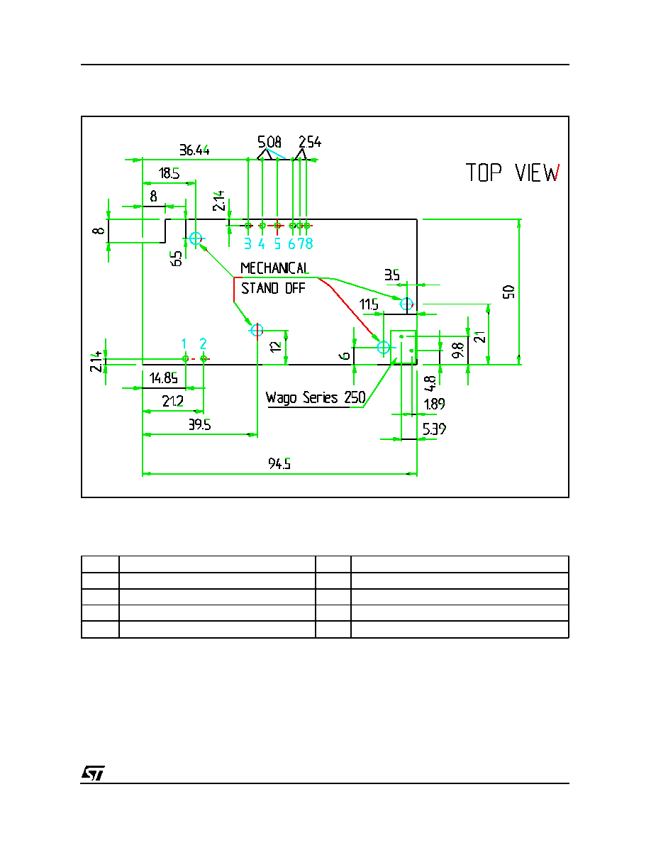
COMBI/E1-I Power Management Module TOP VIEW (dimensions in mm
PIN CONFIGURATION
Input 1 (Vin 1: 230Vac) apply to the WAGO Series connector bottom right in the TOP VIEW
Pin No
Function
Pin No
Function
1
DC "U inteface" input (in 2)
5
Out 2: +/-40 V output
2
DC"U inteface" input (in 2)
6
Out 3: Logic output (NPM)
3
Out 1: +5V output
7
Out 4: PS 2
4
Out common ground GND
8
Out 5: PS 1
COMBI/E1-I
5/6