
1/8
January 2002 - Ed: 3B
s
High breakdown voltage capability
s
High frequency operation
s
Specified turn on switching characteristics
s
Very fast recovery diode
s
Low static and peak forward voltage drop for low
dissipation
s
Insulated package (ISOWATT220AC, TO-220FPAC):
Insulating voltage = 2000V DC
Capacitance = 12pF
s
Planar technology allowing high quality and best
electrical characteristics
FEATURES AND BENEFITS
High voltage diode especially designed for
horizontal deflection stage in standard and high
resolution displays for TV's and monitors.
This
device
is
packaged
in
TO-220AC,
ISOWATT220AC and TO-220FPAC (insulated
package).
DESCRIPTION
I
F(AV)
6 A
V
RRM
1500 V
V
F
(max)
1.65 V
trr (max)
135 ns
MAIN PRODUCTS CHARACTERISTICS
Symbol
Parameter
Value
Unit
V
RRM
Repetitive peak reverse voltage
1500
V
I
F(RMS)
RMS forward current
15
A
I
FSM
Surge non repetitive forward current
tp = 10ms
sinusoidal
75
A
T
stg
Storage temperature
- 65 to 150
�C
T
j
Maximum operating junction temperature
150
�C
ABSOLUTE MAXIMUM RATINGS
DTV1500Mxx
�
(CRT HORIZONTAL DEFLECTION)
HIGH VOLTAGE DAMPER DIODE
K
A
TO-220FPAC
DTV1500MFP
A
K
K
A
ISOWATT220AC
DTV1500MF
K
A
TO-220AC
DTV1500MD

DTV1500Mxx
2/8
Symbol
Parameter
Test Conditions
Value
Unit
Typ
Max
I
R
*
Reverse leakage current
V
R
= 1500V
Tj = 25�C
100
�
A
Tj = 125�C
100
1000
�
A
V
F
**
Forward voltage drop
I
F
=6A
Tj = 25�C
1.4
2.2
V
Tj = 125�C
1.20
1.65
pulse test : * tp = 5 ms ,
< 2%
** tp = 380
�
s,
< 2%
STATIC ELECTRICAL CHARACTERISTICS
Symbol
Parameter
Value
Unit
R
th(j-c)
Junction to Case thermal resistance
TO-220FPAC
5.4
�C/W
ISOWATT220AC
4.75
TO-220AC
2.5
THERMAL RESISTANCE
Symbol
Parameter
Test Conditions
Value
Unit
Typ
Max
t
rr
Reverse recovery
time
Tj = 25�C
I
F
= 1 A dI
F
/dt = -50A/
�
s
V
R
= 30V
110
135
ns
t
rr
Reverse recovery
time
Tj = 25�C
I
F
= 100mA I
R
= 100mA
I
RR
= 10mA
750
ns
RECOVERY CHARACTERISTICS
Symbol
Parameter
Test Conditions
Value
Unit
Typ
Max
t
fr
Forward
recovery time
Tj = 100�C
I
F
= 6 A
dI
F
/dt = 80 A/
�
s
V
FR
= 3 V
570
ns
V
Fp
Peak forward
voltage
Tj = 100�C
I
F
= 6A
dI
F
/dt = 80 A/
�
s
21
28
V
To evaluate the maximum conduction losses use the following equation :
P = 1.37 x I
F(AV)
+ 0.047 x I
F
2
(RMS)
TURN-ON SWITCHING CHARACTERISTICS
DTV1500Mxx
3/8
0
1
2
3
4
5
6
0.0
0.5
1.0
1.5
2.0
2.5
Ip(A)
PF(av)(W)
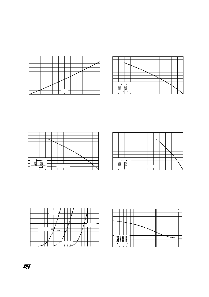
Fig. 1: Power dissipation versus peak forward cur-
rent (triangular waveform,
= 0.45)
0
25
50
75
100
125
150
0
2
4
6
8
10
12
Tcase(�C)
IF(av)(A)
T
=tp/T
tp
Fig. 2-1: Average current versus case tempera-
ture (
= 0.5) (TO-220FPAC)
0
25
50
75
100
125
150
0
2
4
6
8
10
12
Tcase(�C)
IF(av)(A)
T
=tp/T
tp
Fig. 2-2: Average current versus case tempera-
ture (
= 0.5) (ISOWATT220AC)
0
25
50
75
100
125
150
0
2
4
6
8
10
12
Tcase(�C)
IF(av)(A)
T
=tp/T
tp
Fig. 2-3: Average current versus case tempera-
ture (
= 0.5) (TO-220AC)
0.4 0.6 0.8 1.0 1.2 1.4 1.6 1.8 2.0 2.2 2.4 2.6 2.8
5.0
10.0
15.0
VFM(V)
IFM(A)
Typical
Tj=125�C
Maximum
Tj=25�C
Maximum
Tj=125�C
Fig. 3: Forward voltage drop versus forward cur-
rent (DTV1500MFP/F/D)
1E-3
1E-2
1E-1
1E+0
0
10
20
30
40
50
t(s)
IM(A)
Tc=100�C
I
M
t
=0.5
Fig. 4-1: Non repetitive surge peak forward current
versus overload duration (TO-220FPAC)

DTV1500Mxx
4/8
1E-3
1E-2
1E-1
1E+0
0
10
20
30
40
50
60
t(s)
IM(A)
Tc=100�C
I
M
t
=0.5
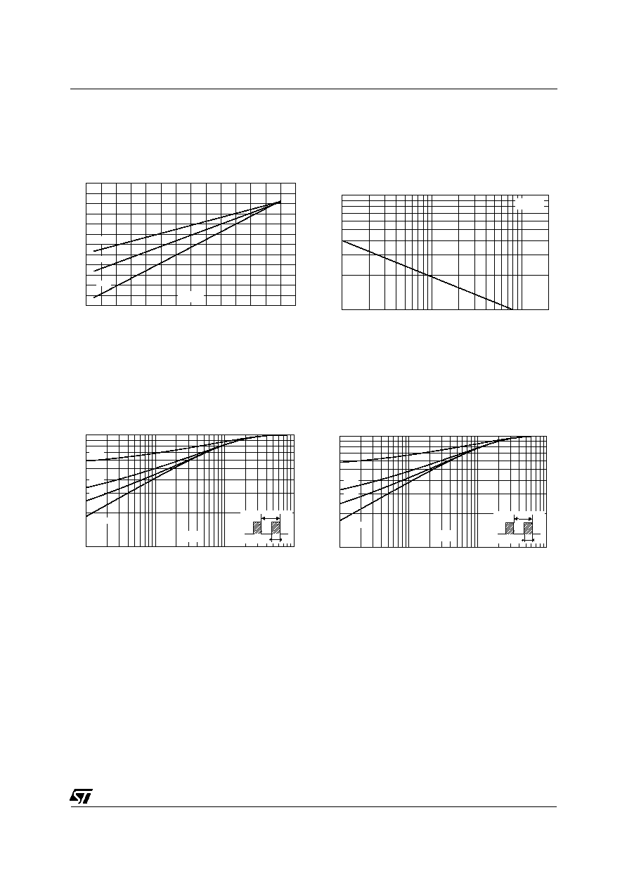
Fig. 4-2: Non repetitive surge peak forward current
versus overload duration (ISOWATT220AC)
1E-3
1E-2
1E-1
1E+0
0
10
20
30
40
50
60
70
80
t(s)
IM(A)
Tc=100�C
I
M
t
=0.5
Fig. 4-3: Non repetitive surge peak forward current
versus overload duration (TO-220AC)
0.1
0.2
0.5
1.0
2.0
5.0
0
200
400
600
800
1000
1200
dIF/dt(A/�s)
Qrr(nc)
IF= 6A
90% confidence
Tj=125�C
Fig. 5: Reverse recovery charges versus dIF/dt.
0.1
0.2
0.5
1.0
2.0
5.0
0.0
0.2
0.4
0.6
0.8
1.0
1.2
1.4
1.6
1.8
2.0
2.2
2.4
dIF/dt(A/�s)
IRM(A)
IF= 6A
90% confidence
Tj=125�C
Fig. 6: Reverse recovery current versus dIF/dt.
0
20
40
60
80
100
120
140
0
5
10
15
20
25
30
35
40
dIF/dt(A/�s)
VFP(V)
IF= 6A
90% confidence
Tj=125�C
Fig. 7: Transient peak forward voltage versus
dIF/dt.
0
20
40
60
80
100
120
140
300
350
400
450
500
550
600
650
700
750
800
dIF/dt(A/�s)
tfr(ns)
IF= 6A
90% confidence
Tj=125�C
VFR=3V
Fig. 8: Forward recovery time versus dIF/dt
DTV1500Mxx
5/8
1
10
100
200
10
20
50
100
VR(V)
C(pF)
Tj=25�C
F=1MHz
Fig. 10: Junction capacitance versus reverse volt-
age applied (typical values)
0
20
40
60
80
100
120
140
0.0
0.2
0.4
0.6
0.8
1.0
1.2
Tj(�C)
VFP
IRM
Qrr
Fig. 9: Dynamic parameters versus junction
temperature
1E-2
1E-1
1E+0
1E+1
0.1
0.2
0.5
1.0
t(s)
K=[Zth(j-c)/Rth(j-c)]
= 0.5
= 0.2
= 0.1
Single pulse
T
=tp/T
tp
Fig. 11-1: Relative variation of thermal impedance
junction
to
case
versus
pulse
duration
(ISOWATT220AC & TO-220FPAC)
1E-3
1E-2
1E-1
1E+0
0.1
0.2
0.5
1.0
tp(s)
K=[Zth(j-c)/Rth(j-c)]
T
=tp/T
tp
= 0.5
= 0.2
= 0.1
Single pulse
Fig. 11-2: Relative variation of thermal impedance
junction
to
case
versus
pulse
duration
(TO-220AC)